
Performing scenario reduction in a circuit design flow

a scenario reduction and circuit design technology, applied in the field of electronic design automation, can solve the problems of increasing the complexity of circuit design, consuming a significant portion of circuit design time, and circuit optimization is a very complex task, and achieve the effect of reducing the number of scenarios

Active Publication Date: 2015-06-02
SYNOPSYS INC
View PDF7 Cites 1 Cited by
  • Summary
  • Abstract
  • Description
  • Claims
  • Application Information

AI Technical Summary

Benefits of technology

[0008]Some embodiments of the present invention provide techniques and systems for reducing the number of scenarios over which a circuit design is optimized. Optimizing a circuit design can involve modifying the circuit design so that one or more design constraints are met. Each scenario in the set of scenarios can be associated with a process corner, an operating condition, and / or an operating mode. During operation, the system can receive a set of scenarios over which the circuit design is to be optimized. Next, the system can compute values of constrained objects in the circuit design over the set of scenarios. A constrained object in the circuit design can be any object in the circuit design (e.g., a net, a gate, a pin or terminal of a gate, a timing end-point, etc.) which is required to meet one or more design constraints in one or more scenarios. The system can then determine a subset of scenarios based partly or solely on the values of the constrained objects, so that if the circuit design meets design constraints in each scenario in the subset of scenarios, the circuit design is expected to meet the design constraints in each scenario in the set of scenarios. For example, the subset of scenarios can be determined using the difference between the actual values of the constrained object and an associated threshold, e.g., the difference between the actual capacitive load on a gate's output and the maximum allowed capacitive load.
[0010]In some embodiments, for each scenario in the set of scenarios, the value of at least one constrained object in the scenario is within a given range of a threshold value associated with the constrained object. In other words, the system can use the range to control the robustness of the scenario reduction process. If the range is high, the starting set of scenarios is much more conservative, and hence, the resulting scenario reduction is more robust. In some embodiments, the range can increase (i.e., the scenario reduction can become more robust or conservative) as the circuit design progresses through a circuit design flow.
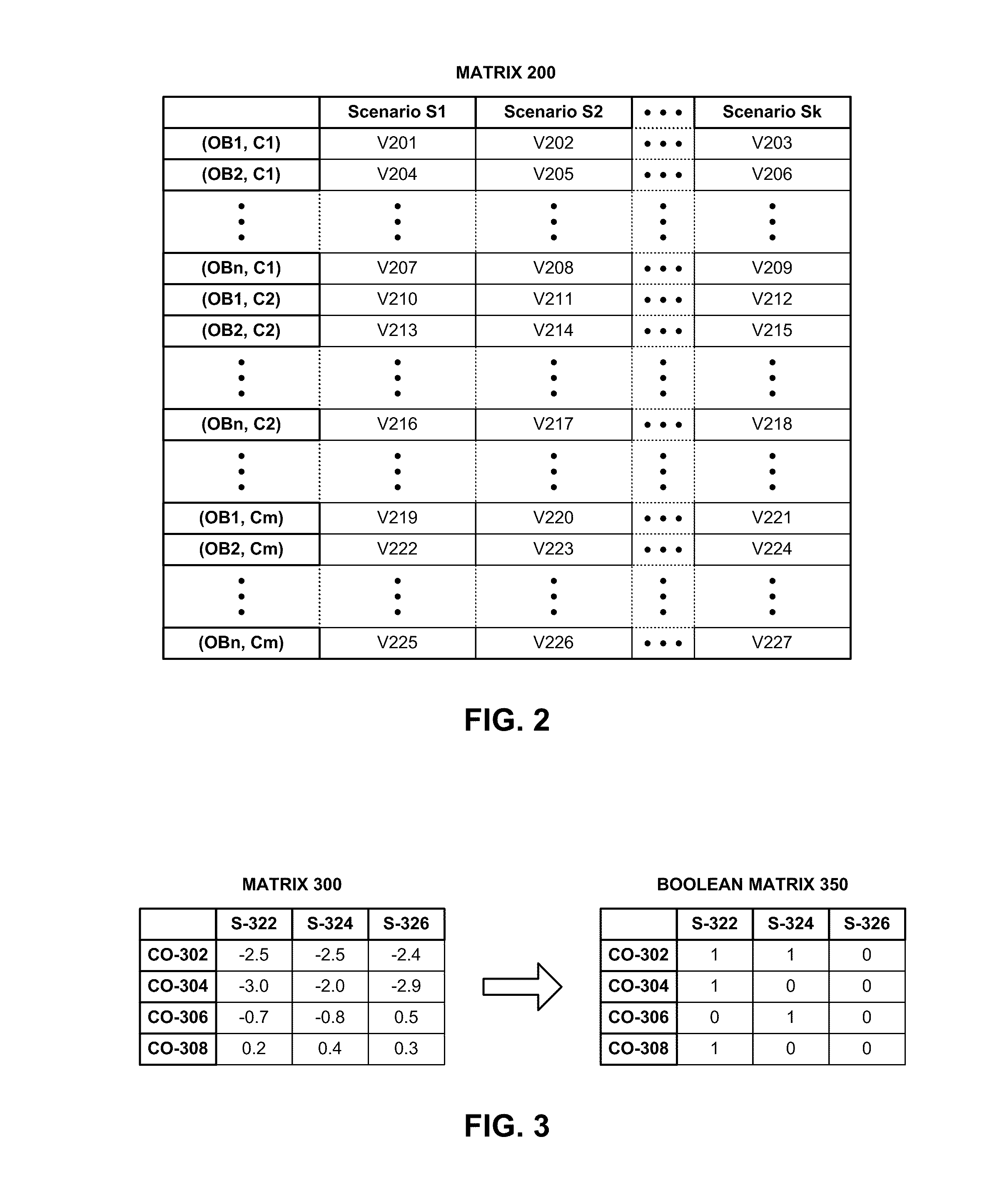
[0011]In some embodiments, the system can relax values of some of the constrained objects in a scenario to obtain relaxed values of the constrained objects, wherein a relaxed value is better (i.e., less worse) than the original value. For example, if the slack for a timing end-point is equal to “−3,” it may be relaxed to “−2.8.” Next, the system can determine the subset of scenarios using the relaxed values of the constrained objects instead of the original values, thereby potentially decreasing the cardinality of the subset of scenarios. The system can employ different criteria for identifying candidate scenarios, and candidate constrained objects within those scenarios, for relaxation. For example, the system can use the ratio of the number of violating constrained objects in a scenario to the total number of violating constrained objects across all scenarios to select a scenario as a candidate for relaxation. The system can perform relaxation iteratively until a relaxation limit is reached. For example, system may determine that the relaxation limit has been reached if at least one of the following three conditions is met: (a) the reduced scenario set converges, i.e. the reduced set of iteration ‘j’ and ‘j+1’ is the same, (b) no additional constrained objects meet the criteria for relaxation, and / or (c) the number of scenarios and / or constrained objects that were relaxed has reached a pre-determined upper limit. In some embodiments, progressively fewer values of constrained objects are relaxed as the circuit design progresses through a circuit design flow, thereby decreasing the amount of relaxation in later stages of the design flow.
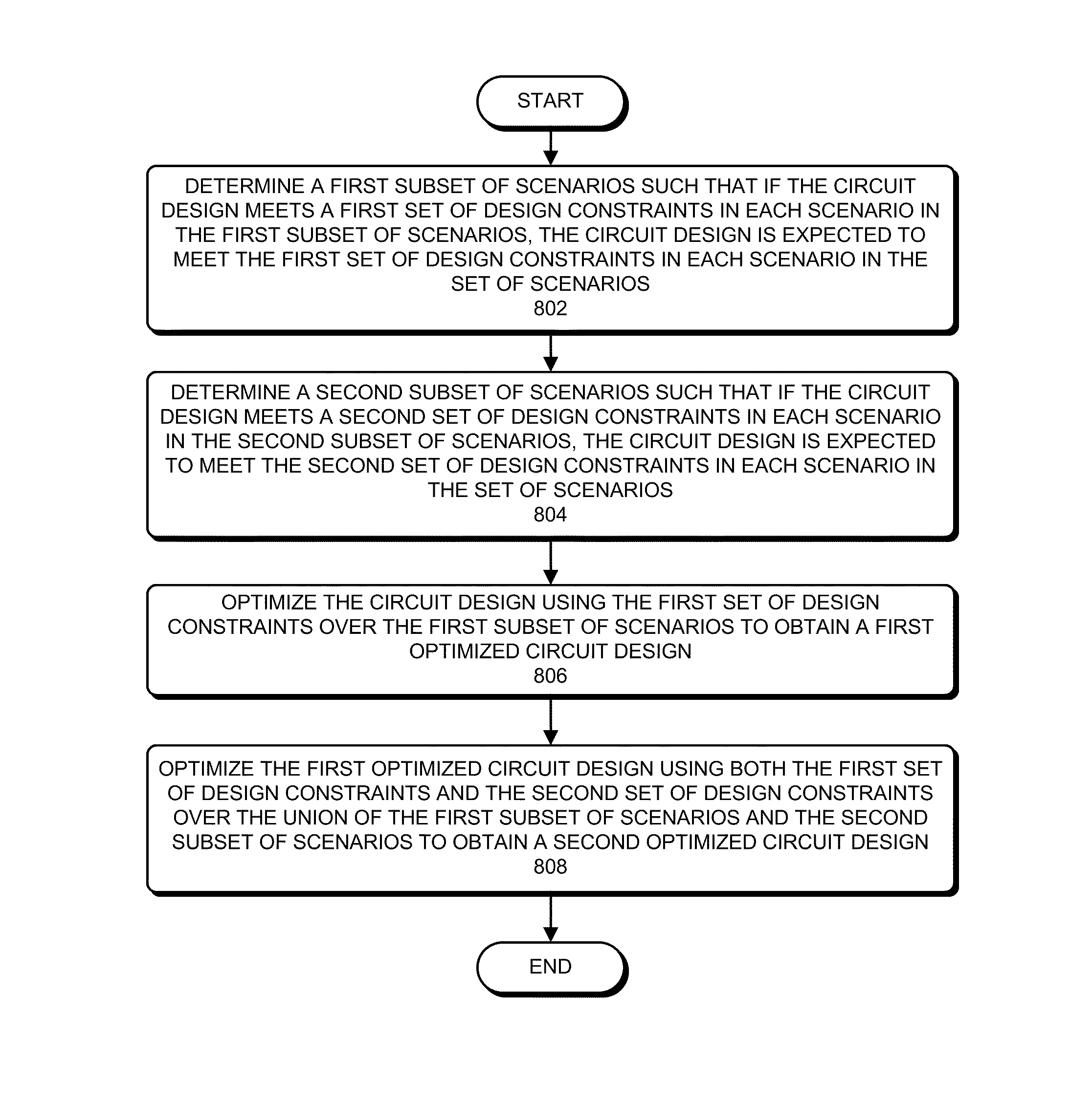
[0013]The system can then optimize the circuit design using the first set of design constraints over the first subset of scenarios to obtain a first optimized circuit design. In some embodiments, performance of the circuit optimization process can be improved by updating circuit information associated with only the first set of design constraints in only the first subset of scenarios. For example, the system can update maximum-delay timing-information in the circuit design for the first subset of scenarios; and not update minimum-delay timing-information in the circuit design for the first subset of scenarios.
[0015]In some embodiments, the system can optimize the first optimized circuit design by iterating through the second subset of scenarios. For example, the system can order scenarios in the second subset of scenarios in decreasing order of relevance and / or importance. Then, in each iteration, a scenario from the second subset of scenarios can be selected, and the first optimized circuit design can be optimized over the first subset of scenarios and the selected scenario from the second subset of scenarios. This can speedup the optimization process since the circuit information associated with only the first subset of scenarios and the selected scenario from the second subset of scenarios needs to be updated.

Problems solved by technology

One reason for the increase in complexity of circuit designs is the introduction of a large number of operational modes (e.g., stand-by, mission, test, etc.).
Circuit optimization is a very complex task which can consume a significant portion of the circuit design time.
It is not surprising, therefore, that the task of optimizing a circuit design across multiple scenarios can easily become impractical if the number of scenarios is too large.
Unfortunately, the number of scenarios over which circuit designs are desired to be optimized is increasing rapidly as semiconductor geometries become smaller and circuit designs become more complex.

Method used


Image

  • Performing scenario reduction in a circuit design flow
  • Performing scenario reduction in a circuit design flow
  • Performing scenario reduction in a circuit design flow

Examples


Embodiment Construction

[0029]The following description is presented to enable any person skilled in the art to make and use the invention, and is provided in the context of a particular application and its requirements. Various modifications to the disclosed embodiments will be readily apparent to those skilled in the art, and the general principles defined herein may be applied to other embodiments and applications without departing from the spirit and scope of the present invention. Thus, the present invention is not limited to the embodiments shown, but is to be accorded the widest scope consistent with the principles and features disclosed herein.

[0030]FIG. 1 illustrates various steps in the design and fabrication of an integrated circuit. The process starts with a product idea 100, which is realized using Electronic Design Automation (EDA) software 110. Chips 170 can be produced from the finalized design by performing fabrication 150 and packaging and assembly 160 steps.

[0031]A design flow that uses ...


PUM


Abstract

Some embodiments of the present invention provide techniques and systems for using scenario reduction in a design flow. The system can use scenario reduction to determine two subsets of scenarios that correspond to two sets of design constraints. Next, the system can optimize the circuit design using one of the sets of design constraints over the associated subset of scenarios. Next, the system can optimize the circuit design using both sets of design constraints over the union of the two subsets of scenarios. In some embodiments, the system can iteratively optimize a circuit design by: performing multiple optimization iterations on the circuit design over progressively larger subsets of scenarios which are determined by performing scenario reduction with relaxation; and performing at least one optimization iteration on the circuit design over a subset of scenarios which is determined by performing scenario reduction without relaxation.

Description

TECHNICAL FIELD[0001]This disclosure relates to electronic design automation (EDA). More specifically, this disclosure relates to methods and apparatuses for performing scenario reduction and using scenario reduction in a design flow.BACKGROUNDRelated Art[0002]The relentless miniaturization and increasing complexity of integrated circuits have been key driving forces behind the rapid advances in computer technology.[0003]The advance to smaller semiconductor geometries has increased the variability in process and operating conditions of integrated circuits. A process corner is a particular set of process conditions under which the circuit design may be manufactured. An operating corner is a particular set of operating conditions (e.g., temperature, voltage) under which the circuit design may operate. The term “corner” can refer to a process corner, an operating corner, or a combination thereof.[0004]One reason for the increase in complexity of circuit designs is the introduction of a...

Claims


Application Information

Patent Timeline
Patent Type & Authority Patents(United States)
IPC IPC(8): G06F17/50
CPCG06F17/504G06F17/5045G06F30/30G06F30/3323
Inventor MOTTAEZ, AMIR H.
Owner SYNOPSYS INC
Learn More