Double loop lasso with single puller wire for bi-directional actuation

a puller wire and lasso technology, applied in the field of improved ablation catheters, can solve the problems of bending and shear combined stresses of puller wires, and tensile stresses, and reducing the predictability of desired deflection

Active Publication Date: 2015-06-09
BIOSENSE WEBSTER (ISRAEL) LTD
View PDF24 Cites 25 Cited by
  • Summary
  • Abstract
  • Description
  • Claims
  • Application Information

AI Technical Summary

Benefits of technology

[0008]In one embodiment, the catheter has an elongated tubular catheter body with at least one lumen, a deflectable intermediate section with at least two off-axis lumens, and a distal assembly with a tubular structure having a generally straight proximal region attached to the deflectable intermediate section and a generally circular main region generally transverse and distal to the proximal region. The distal assembly has an elongated rod-like support member with shape memory extending through the length of the distal assembly. An extruded non-conductive cover covers the support member which extends through a first lumen of the cover. The first lumen is sized to provide a tight or interference fit with the support member to minimize free play and micro-movements between the cover and the support member. Lead wires for electrodes carried on the distal assembly extend through a second lumen formed in the cover. The cover is constructed of a material that readily conforms to the shape and configuration of the support member without heat treatment.
[0010]In one embodiment, the support member of the distal assembly is anchored at its proximal end in a connector section extending between the deflectable intermediate section and the distal assembly. The connector section has a central lumen filled with adhesive to form an adhesive volume in which a proximal end of the support member is anchored. To that end, a proximal end of the support member is flattened to provide a more planar form, with more bonding surface. The proximal end is also serrated to provide an irregular bonding surface. Accordingly, the proximal end potted in the adhesive resists rotational and axial movements that may otherwise loosen or detach the support member and the distal assembly from the catheter.
[0011]In one embodiment, the each proximal end portion of the puller wire is surrounded by a compression coil that is flexible but resists compression. Accordingly, a distal end of the compression coil defines a location for initiation of a deflection curvature when the puller wire is acted on by deflection mechanism in the control handle. By providing a first compression coil with a longer length and a second compression coil with a shorter length, each proximal end portion of the puller wire has a different deflection initiation location and hence a different deflection curvature to provide nonsymmetrical bi-directional deflection.
[0012]In one embodiment, a location sensor is potted in the adhesive volume of the connector section. The sensor has a housing that encloses at least one sensing coil. The housing is generally encased in a protective tubing which isolates the at least one sensing coil from the adhesive volume and protects it from torsional and / or axial tension / compression forces acting on the adhesive volume that may damage the sensor.

Problems solved by technology

However, these anchoring means can be offset from the lumens thus subject the puller wire to combined stresses of bending and shear along with tensile stresses.
Moreover, tip deflection can also be skewed and off plane reducing predictability of desired deflection.
Another issue with catheters arises from free play and slippage between the support member of the distal assembly and the nonconductive cover which reduces the accuracy of the mapping and ablation procedures.
Furthermore, the support member can also dislodge or detach from the catheter when the distal assembly is subjected to repeated and / or excessive contact forces.
Additionally, repeated and / or excessive contact forces can also damage components, such as a location sensor, that are near where the support member is anchored to the catheter.

Method used


Image

  • Double loop lasso with single puller wire for bi-directional actuation
  • Double loop lasso with single puller wire for bi-directional actuation
  • Double loop lasso with single puller wire for bi-directional actuation

Examples


Embodiment Construction

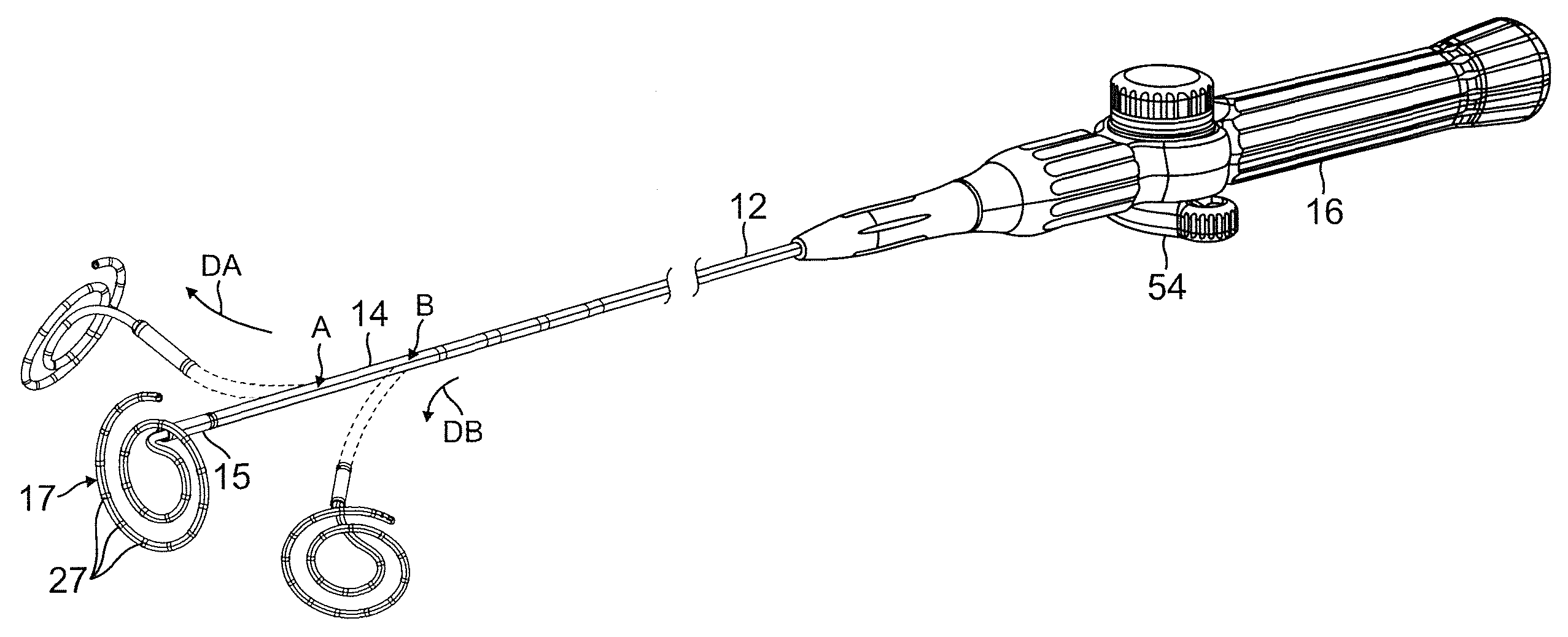
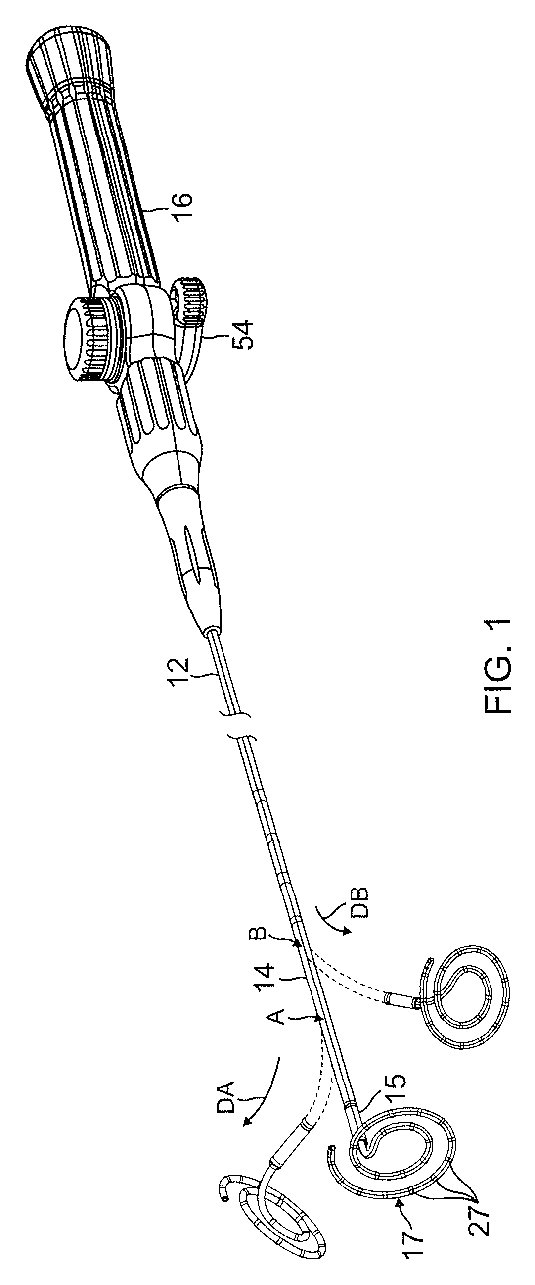
[0026]As shown in FIG. 1, a catheter 10 of the present invention comprises an elongated catheter body 12 having proximal and distal ends, a deflectable distal section 14 at the distal end of the catheter body, and a control handle 16 at the proximal end of the catheter body. The catheter also includes a distal assembly 17 that is mounted to a connector section 15 at a distal end of the distal section 14. The distal assembly carries a plurality of electrodes 27 adapted for mapping and / or ablation.

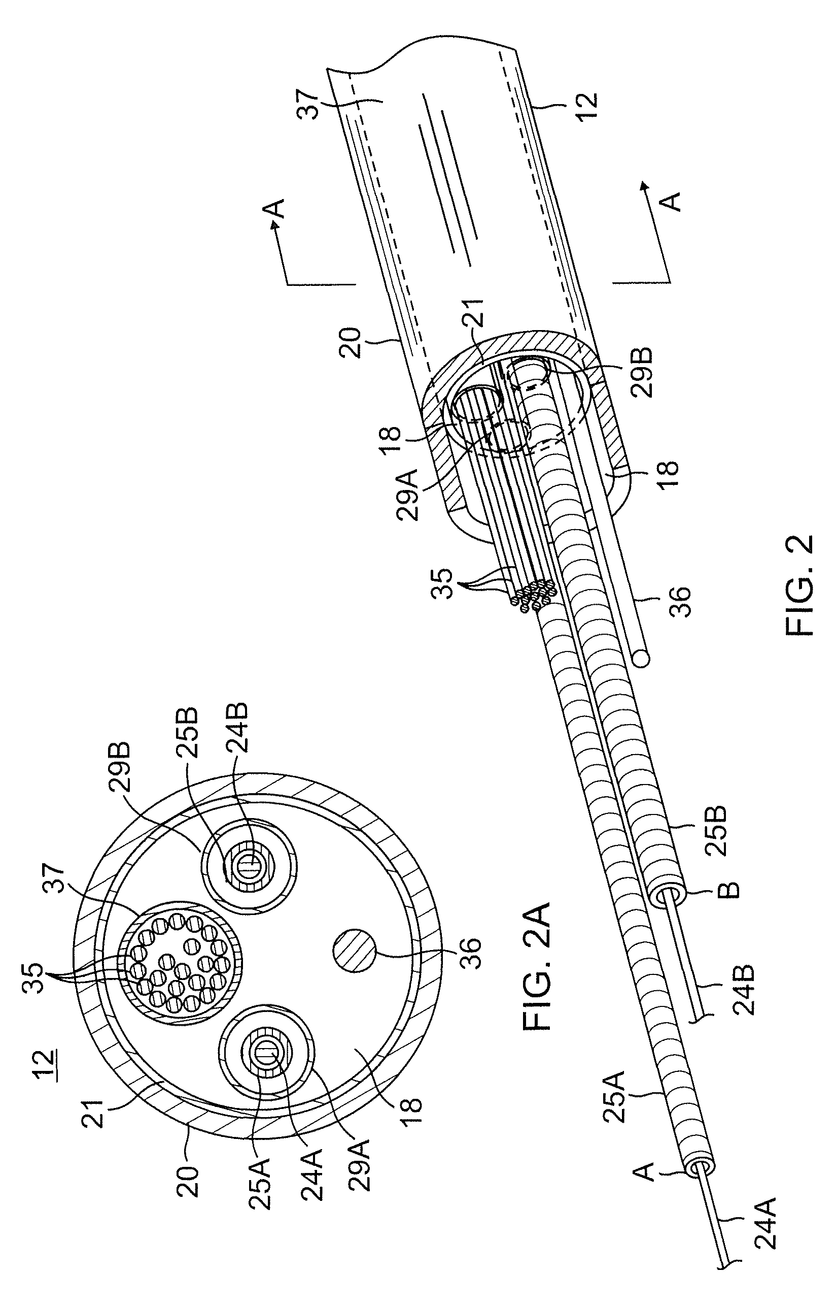
[0027]With reference to FIGS. 2 and 2A, the catheter body 12 comprises an elongated tubular construction having a single, axial or central lumen 18. The catheter body 12 is flexible, i.e. bendable, but substantially non-compressible along its length. The catheter body 12 can be of any suitable construction and made of any suitable material. In the disclosed embodiment, the catheter body includes at least an outer wall 20 (e.g., of PEBAX or Pellethane). The outer wall 20 may include an imbedd...


PUM


Abstract

A catheter has a distal assembly with at least one loop, if not two, with ring electrodes. The distal assembly has an elongated support member covered by an extruded form having two lumens, one sized for nonslip tight fit with the support member. A single continuous puller wire for bidirectional deflection is pre-bent into two long portions and a U-shape bend therebetween. The U-shape bend is anchored at a distal end of a deflectable section which is reinforced by at least one washer having at least two holes, each hole axially aligned with a respective lumen in the deflectable section. Each hole is centered with a lumen so that each puller wire portion therethrough is straight and subjected to tensile force only. A proximal end of the support member is flattened and serrated to provide a better bonding to the distal end of the deflectable section.

Description

FIELD OF THE INVENTION[0001]The present invention relates to an improved ablation catheter that is particularly useful for mapping or ablating in a tubular region of or near the heart.BACKGROUND OF THE INVENTION[0002]Electrode catheters have been in common use in medical practice for many years. They are used to stimulate and map electrical activity in the heart and to ablate sites of aberrant electrical activity. Atrial fibrillation is a common sustained cardiac arrhythmia and a major cause of stroke. This condition is perpetuated by reentrant wavelets propagating in an abnormal atrial-tissue substrate. Various approaches have been developed to interrupt wavelets, including surgical or catheter-mediated atriotomy. Prior to treating the condition, one has to first determine the location of the wavelets. Various techniques have been proposed for making such a determination, including the use of catheters with a distal assembly that is adapted to measure activity and / or ablate within ...

Claims


Application Information

Patent Timeline
Patent Type & Authority Patents(United States)
IPC IPC(8): A61B5/042A61B18/14A61B5/00A61M25/01A61B18/00
CPCA61B5/042A61B5/6856A61B5/6857A61B18/1402A61M25/0147A61M25/0136A61M25/0152A61B2018/0016A61B2018/00839A61B2018/1407A61B2018/1435A61M2025/015A61B2018/00351A61B2018/1467A61M2025/0681A61B2034/2051A61B18/1492A61B5/283A61B2562/0209A61B5/287A61B5/4836A61B2018/00071A61B2018/0091A61B18/1442A61B2018/00077A61B18/14A61B5/05A61B18/082A61B2018/00702A61B2018/1405A61B5/0082A61B18/12A61B18/24A61B5/053A61B2018/00779A61B5/1473A61B5/271A61B2018/00964A61B2018/00184A61B5/0084A61B5/0048A61B5/0215A61M25/0133A61M25/0068A61B5/6869A61B5/273A61B5/6852A61B5/6855A61M25/0023A61M2025/0163A61M25/0071A61M25/0026A61B5/065A61B2018/00577A61B2018/1465A61M25/0662
Inventor BUI, JULIEGALVAN, OSCARJIMENEZ, JOSENGUYEN, THANHPADILLA, RICARDOSELKEE, THOMAS V.
Owner BIOSENSE WEBSTER (ISRAEL) LTD
Why Eureka
Try Eureka