Electrothermal heater

a heater and electro-thermal technology, applied in the direction of heater elements, ohmic-resistance electrodes, heating element materials, etc., can solve the problems of increasing drag, reducing the ability of an aerofoil to perform the intended function, and undesirable in-flight ice formation on the external surface of the aircraft, so as to reduce the current induced, reduce the resistance layer, and the effect of low resistan

a heater and electro-thermal technology, applied in the direction of heater elements, ohmic-resistance electrodes, heating element materials, etc., can solve the problems of increasing drag, reducing the ability of an aerofoil to perform the intended function, and undesirable in-flight ice formation on the external surface of the aircraft, so as to reduce the current induced, reduce the resistance layer, and the effect of low resistan

US20120298803A1Inactive Publication Date: 2012-11-29GKN AEROSPACE SERVICES LTD

Image

  • Electrothermal heater
  • Electrothermal heater
  • Electrothermal heater

Examples


first embodiment

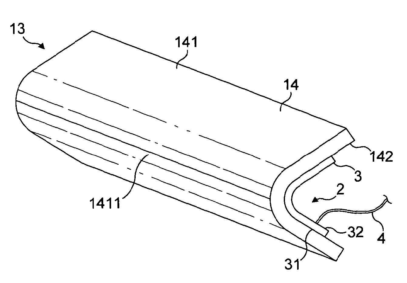
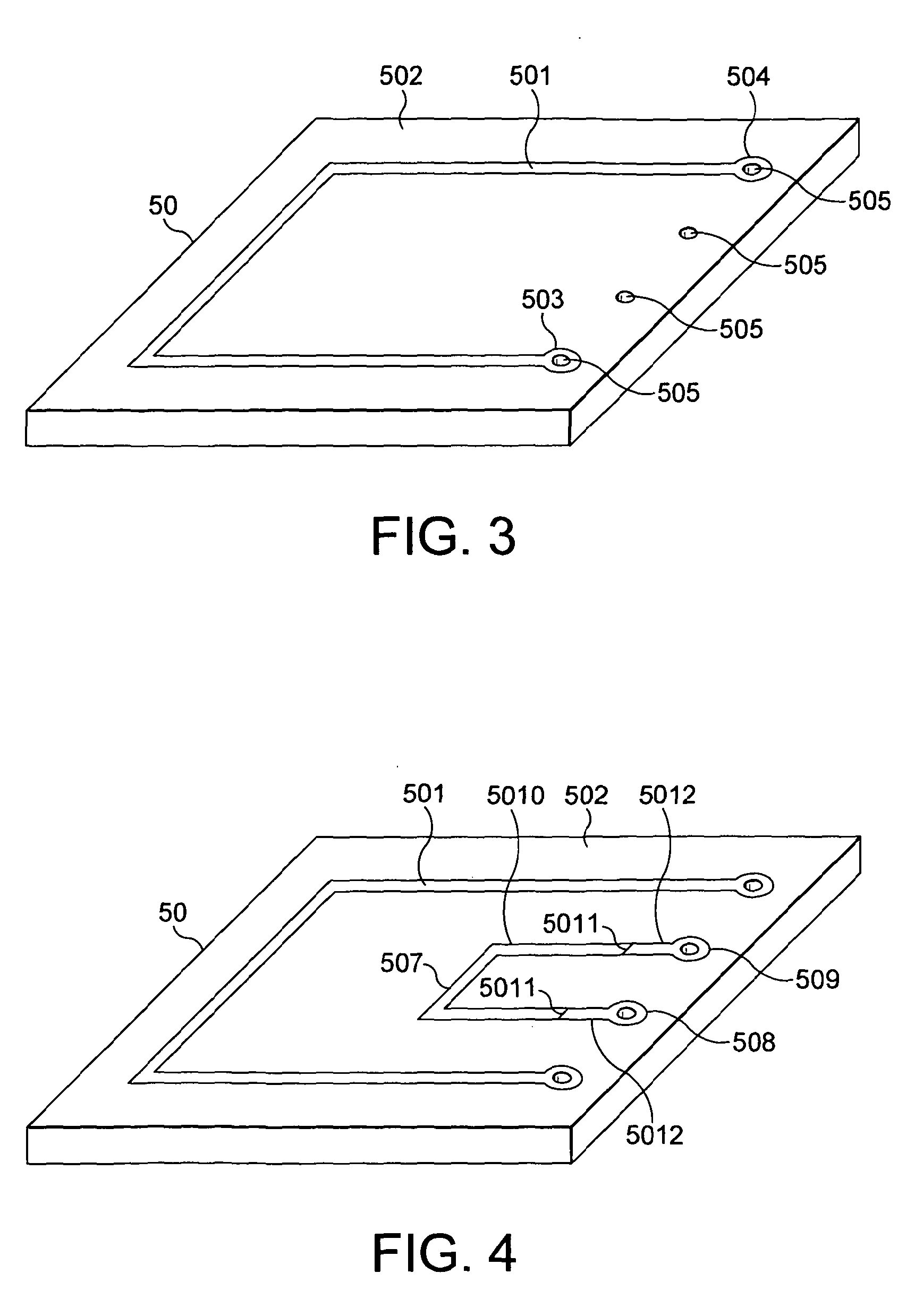
[0089]An assembly process for producing a heater mat in accordance with the present invention will now be described with reference to FIGS. 3-19 which depict, in a very diagrammatic manner, the components of the heater mat and how they are assembled together to produce the heater mat and how the heater mat is then bonded to an erosion shield.

[0090]The components shown in FIGS. 3-19 are very diagrammatic. For example, in relation to the dielectric layer 50 shown in FIG. 3, the thickness has been exaggerated for the sake of clarity. Also, the width and length of the layer have been reduced for the sake of clarity. In a practical embodiment, the dielectric layer would be generally rectangular and would be a sheet having a width ranging typically from 0.25 m to 1 m and a length ranging from typically 1 m to 4 m. In use, the width of the sheet will usually wrap around the chord at the leading edge of the wing, and the length of the sheet will usually extend along the span of the wing. Th...

second embodiment

[0171]There has also been described FIGS. 20-28 wherein the dielectric layers comprise a stack containing first, second, third, fourth and fifth dielectric layers; the heater element is positioned between the first and second dielectric layers; the first ground plane is positioned between the second and third dielectric layers; the first end of the first connector is positioned between the third and fourth dielectric layers; and the second ground plane is positioned between the fourth and fifth dielectric layers.


PUM


Abstract

An electrothermal heater (2) for an ice protection system for an aircraft (1) or the like is provided with improved protection against lightning strikes. The heater (2) comprises a laminated heater mat (3) formed from dielectric layers (51-54) and a heater element (501). A first connector (41) has a first end (415) which is embedded in the heater mat (3) and is electrically connected to the heater element (501) and a second end which extends away from the heater mat for connection to a heater control unit (6). The heater mat (3) further includes first and second conductive ground planes (71, 72) and the first end (415) of the first connector (41) is positioned between the first and second ground planes so as to be shielded thereby and so as to reduce the current induced therein during a lightning strike.

Description

FIELD OF THE INVENTION[0001]The present invention relates generally to an electrothermal ice protection system suitable for use in an aircraft or other aerodynamic structure such as a blade of a wind turbine to prevent ice from forming and / or to remove ice that has already formed. These two functions may be termed anti-icing and de-icing, respectively.BACKGROUND OF THE INVENTION[0002]For an aircraft, the in-flight formation of ice on the external surface of the aircraft is undesirable. The ice destroys the smooth flow of air over the aircraft surface, increases drag and decreases the ability of an aerofoil to perform its intended function.[0003]Also, built-up ice may impede the movement of a movable control surface such as a wing slat or flap. Ice which has built up on an engine air inlet may be suddenly shed in large chunks which are ingested into the engine and cause damage.[0004]It is therefore common for aircraft, and particularly commercial aircraft, to incorporate an ice prote...

Claims


Application Information

Patent Timeline
29 Nov 2012
Publication
US20120298803A1
IPC
B64D15/12; H05B3/03; H05B3/18; H05B3/34
CPC
B64D15/12; B64D45/02; Y02E10/722; F03D11/0025; Y02E10/721; F03D1/065; F03D80/40; Y02E10/72
Inventors
ENGLISH, PETER; LEWIS, STUART MARTIN