Clamp mechanism and related printer

a technology of a clamping mechanism and a printer, which is applied in the direction of printing presses, thin material handling, printing, etc., can solve the problem that the conventional printer cannot print high-quality patterns, and achieve the effect of increasing the market competition of products and facilitating printing quality

Inactive Publication Date: 2015-06-09
HI TOUCH IMAGING TECH CO LTD
View PDF21 Cites 2 Cited by
  • Summary
  • Abstract
  • Description
  • Claims
  • Application Information

AI Technical Summary

Benefits of technology

[0017]The printer of the present invention utilizes the clamp mechanism to fix the front end of the printing medium (the paper), and rotates the drum to move a position of the clamp mechanism relative to the supporter. Because the clamp mechanism of the present invention clamps the front end of the printing medium in the printing procedures, the thorns of the clamping component do not form a series of pinholes on the printing medium along the conveying path. Therefore, an area of the printing medium whereon a pattern is formed is not damaged by the printer of the present invention, so the present invention not only can execute duplex printing by the same conveying path (the printing medium), but also can have preferable printing quality, so as to increase market competition of the product.

Problems solved by technology

However, drawbacks of the apertures are detected by eyes and hand touch easily, so the conventional printer can not utilized to print the high quality pattern.
Thus design of a printer with preferable printing quality is an important issue in the mechanical industry.

Method used


Image

  • Clamp mechanism and related printer
  • Clamp mechanism and related printer
  • Clamp mechanism and related printer

Examples


Embodiment Construction

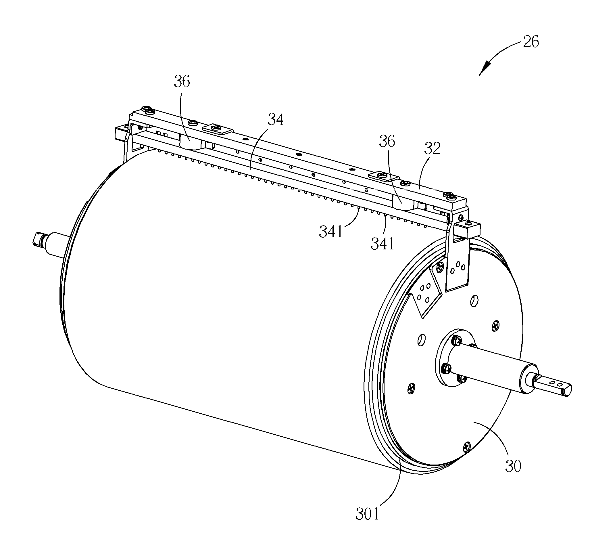
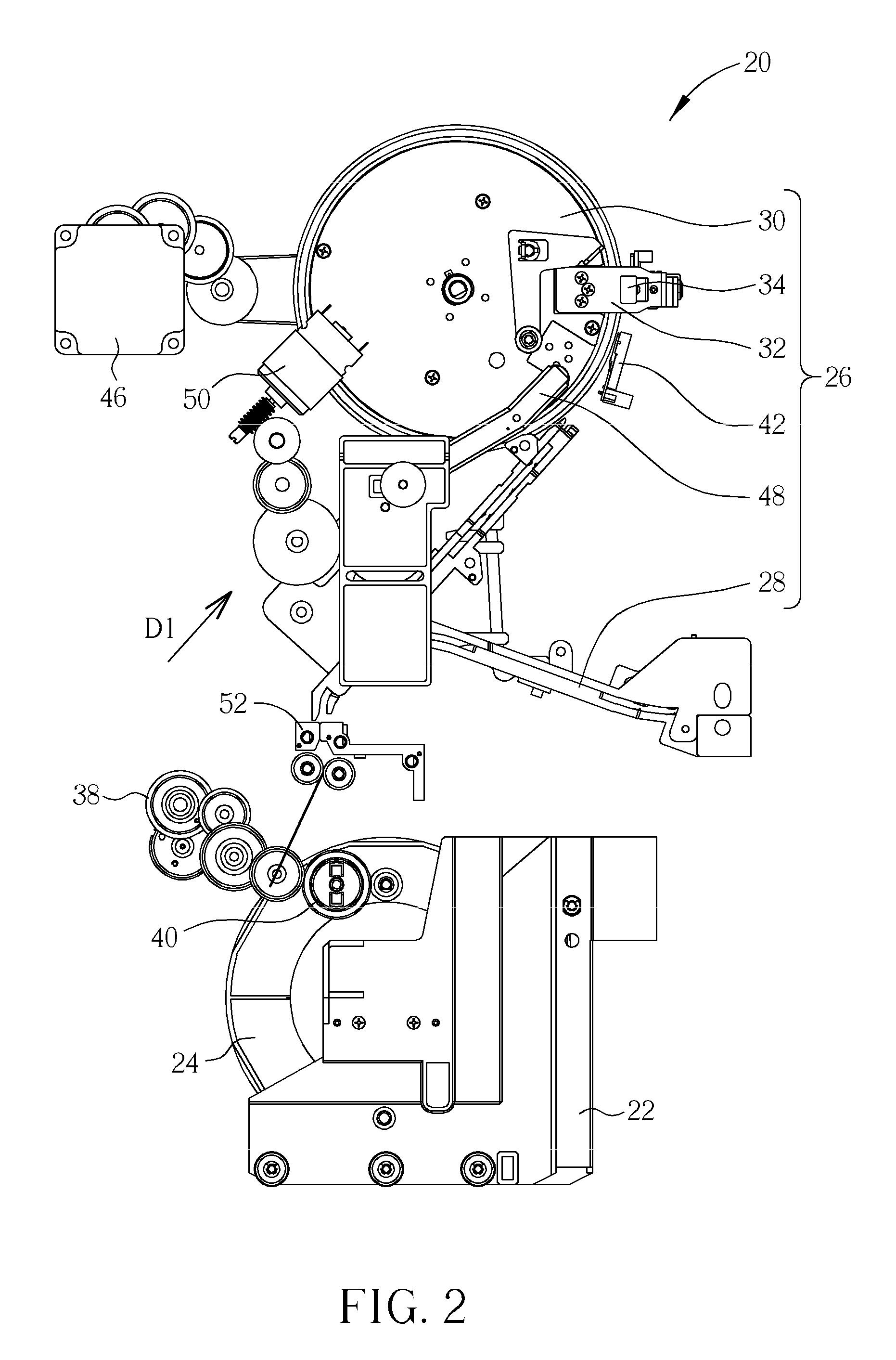
[0026]Please refer to FIG. 2. FIG. 2 is a diagram of a printer 20 according to an embodiment of the present invention. The printer 20 includes a supporter 22 for supporting a printing medium 24, such as paper. The supporter 22 can be disposed on a bottom of a casing (not shown in the figure) of the printer 20. The printer 20 further includes a clamp mechanism 26 for stably clamping the printing medium 24 and increasing print quality. Please refer to FIG. 3. FIG. 3 is a diagram of the clamping mechanism 26 at an open state according to the embodiment of the present invention. The clamp mechanism 26 includes a base 28, a drum 30 pivotably disposed on the base 28, a frame 32 disposed on the drum 30, a clamping component 34 movably disposed on the frame 32, and two resilient components 36 respectively disposed between the frame 32 and the clamping component 34. The clamping component 34 shown in FIG. 3 does not contact the drum 30, so the printing medium 24 can move through a gap betwee...


PUM

PropertyMeasurementUnit
tensionaaaaaaaaaa
areaaaaaaaaaaa
resilient recovering forceaaaaaaaaaa

Abstract

A clamp mechanism for fixing a printing medium is disclosed in the present invention. The clamp mechanism includes a base, a drum pivotably disposed on the base, a frame disposed on the drum, a clamping component movably disposed on the frame for clamping an end of the printing medium with the drum, and a resilient component disposed between the frame and the clamping component for pressing the clamping component on a surface of the drum so as to clamp the end of the printing medium.

Description

BACKGROUND OF THE INVENTION[0001]1. Field of the Invention[0002]The present invention relates to a clamp mechanism and a related printer, and more particularly, to a clamp mechanism and a related printer that do not hurt the printing medium.[0003]2. Description of the Prior Art[0004]Please refer to FIG. 1. FIG. 1 is a diagram of a conveying mechanism 10 in the prior art. The conveying mechanism 10 includes a print head 12, a platen roller 14, a pinch roll 16 and a capstan roller 18. The printing medium moves from the print head 12 and the platen roller 14 to the pinch roll 16 and the capstan roller 18. The print head 12 presses the platen roller 14, which means the platen roller 14 clamps the printing medium with the print head 12. The pinch roller 16 is rotated by a driving motor, and conveys the printing medium according to structure of the capstan roller 18, so that predetermined dye on a ribbon can be transferred to the printing medium for forming the pattern by the print head 1...

Claims


Application Information

Patent Timeline
Patent Type & Authority Patents(United States)
IPC IPC(8): B41F21/00B65H19/29B65H20/02B41F27/12B41F1/28
CPCB65H20/02B65H19/29B41F1/28B65H2301/522B65H2403/942B65H2801/12H04N1/08H04N1/0813H04N1/0839
Inventor LIAO, KU-FENG
Owner HI TOUCH IMAGING TECH CO LTD
Why Eureka
Try Eureka