
Signal block sequence processing method and signal block sequence processing apparatus

a signal block sequence and processing method technology, applied in the field of signal block sequence processing methods and signal block sequence processing apparatuses, can solve the problems of inability to transfer signals of users utilizing ifg and pr for their own purposes on otn, lack of compatibility of direct mapping schemes, and inability to standardize direct mapping schemes, so as to improve error robustness, improve clock speed, and reduce bit rate

Active Publication Date: 2015-06-09
NIPPON TELEGRAPH & TELEPHONE CORP
View PDF17 Cites 4 Cited by
  • Summary
  • Abstract
  • Description
  • Claims
  • Application Information

AI Technical Summary

Benefits of technology

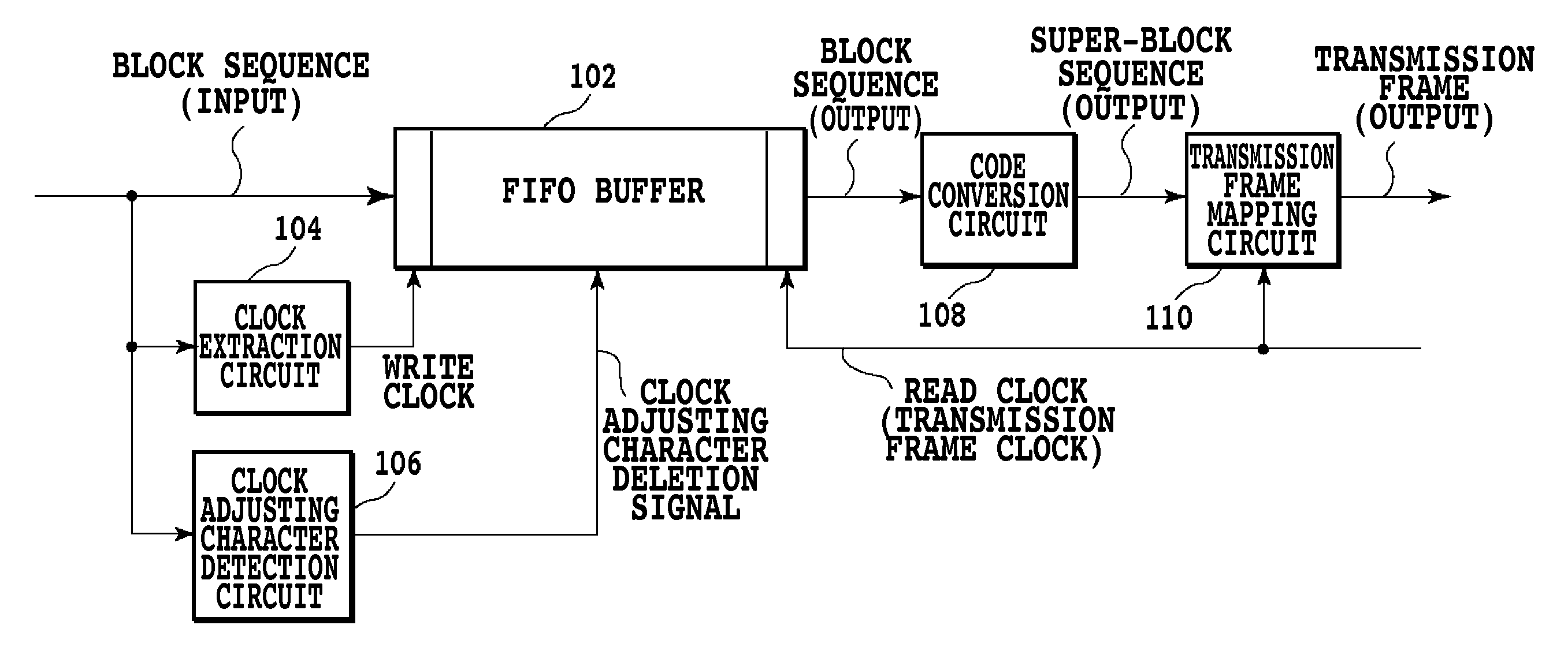
[0024]The present invention has been developed in view of these problems. An object of the present invention is to provide a signal block sequence processing method and a signal block sequence processing apparatus which reduce the bit rate used to communicate a signal block composed of a signal block header and a signal block payload, thus enabling the use of a standardized method and an existing system even if LAN and WAN differ in interface speed.
[0042]The present invention can provide a signal block sequence processing method and a signal block sequence processing apparatus which enable a standardized method, an existing system, or a system with an increase in clock speed suppressed to be utilized even with a difference in interface speed between LAN and WAN. The present invention can also provide a signal block sequence processing method and a signal block sequence processing apparatus which can provide a particular block type value to improve error robustness. The present invention can further provide a signal block sequence processing method and a signal block sequence processing apparatus which utilize an excess bandwidth resulting from a reduced bit rate to transmit FEC (Forward Error Correction), thus enabling bit error robustness to be improved without increasing an overall bit rate.

Problems solved by technology

Thus, signals of users utilizing IFG and PR for their own purposes cannot be transferred on OTN.
Furthermore, the direct mapping scheme allows all the bits to be transmitted but has not been standardized yet.
Thus, the Direct mapping scheme lacks compatibility.
Furthermore, the 64B / 66B block code is excellent in the detection of bit errors but has no function to correct errors.
Thus, the 512B / 513B block coding does not have high robustness to block synchronization.
A possible 1-bit error in the block type value may cause a serious error in the entire block.
Thus, in Non-Patent Document 7, the redundant bit length of the error-correcting code is insufficient for the information bit length, resulting in an insufficient correctable burst error length.
Moreover, the error-correcting code used is designed specifically for correction of burst errors and its robustness to random errors is low.

Method used


Image

  • Signal block sequence processing method and signal block sequence processing apparatus
  • Signal block sequence processing method and signal block sequence processing apparatus
  • Signal block sequence processing method and signal block sequence processing apparatus

Examples


first embodiment

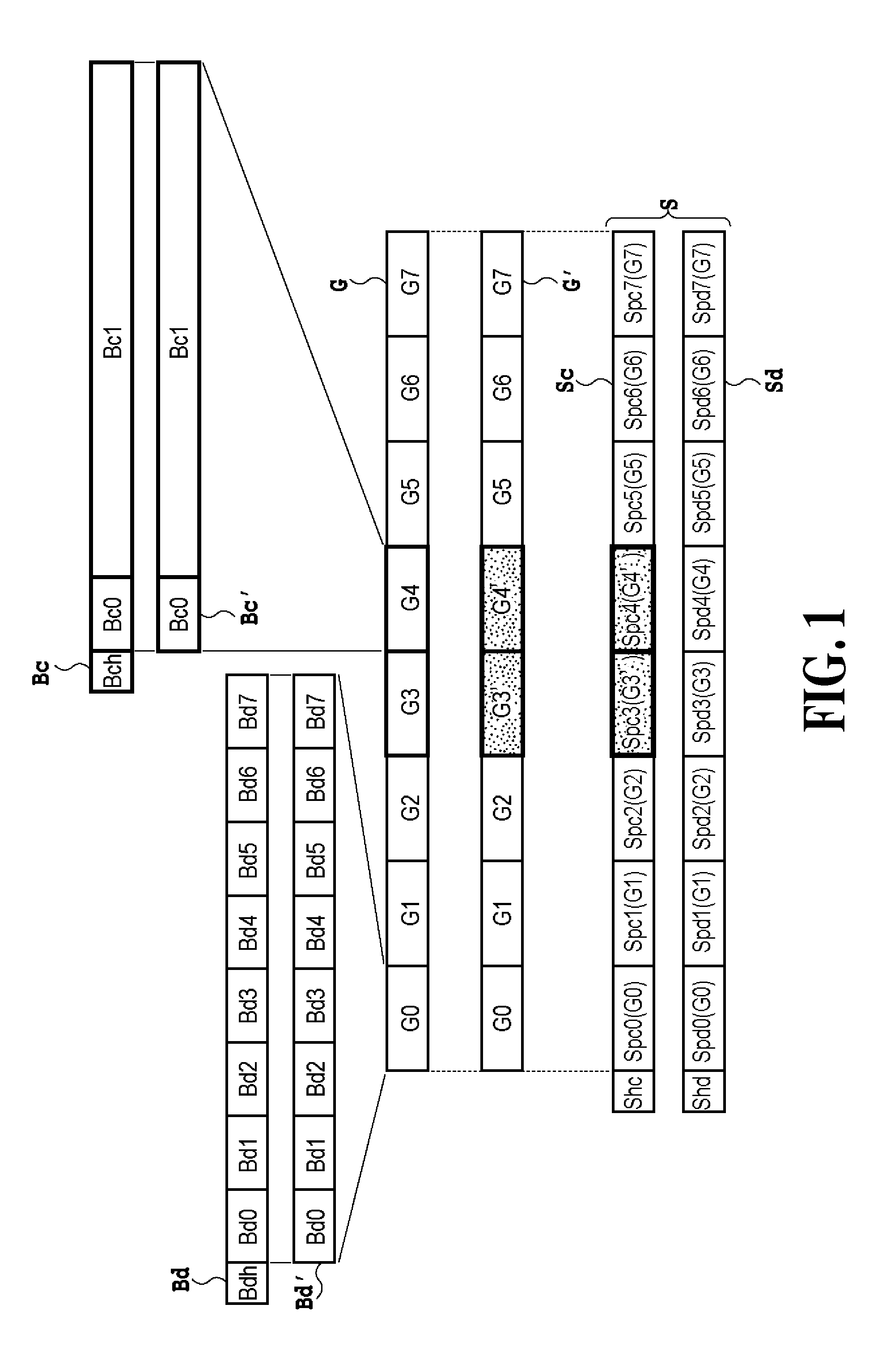
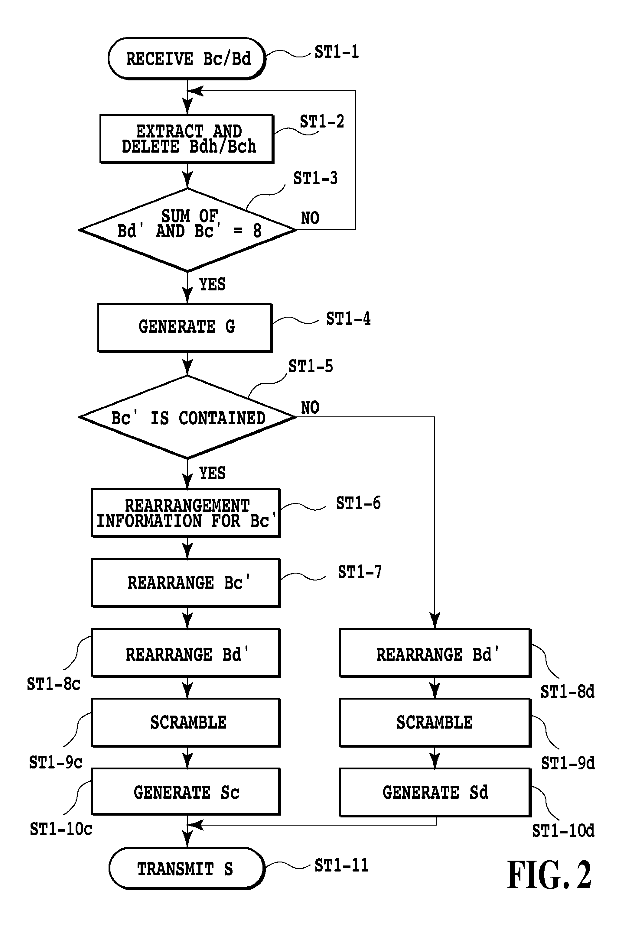
[0129]As described above, according to the present invention, a signal block composed of a signal block payload and a signal block header is processed, and the resultant super-block is output. In the series of processes, signal block headers are deleted to reduce the bit rate at which the super-block is transmitted. Furthermore, according to the present invention, the super-block is processed, and the signal block on which the super-block is based is output.

[0130]A first embodiment of the present invention will be described with reference to the drawings.

[0131]FIG. 1 is a diagram schematically showing how signal blocks are processed. In FIG. 1, a signal block payload in which data is contained (in the specification, this signal block payload is referred to as a data block payload) is denoted by Bd′. A signal block payload in which a control code is contained (in the specification, this signal block payload is referred to as a control block payload) is denoted by Bc′. Furthermore, a ...

second embodiment

[0185]As described above, according to the present invention, a sequence of signal blocks each composed of a signal block payload and a signal block header is input and processed, and the resultant super-block is output. In the series of processes, signal block headers and a part or the whole of each signal block payload composed only of clock adjusting characters are deleted to reduce the bit rate at which the super-block is transmitted. Furthermore, according to the present invention, an input super-block is processed, and the signal blocks based on which the super-block has been generated are output (restored).

[0186]A second embodiment of the present invention will be described below with reference to the drawings.

[0187]FIG. 15 is a diagram schematically showing how signal blocks are processed. In FIG. 15, an input sequence of signal blocks is denoted by B. A signal block payload in which data is contained is denoted by Bd′. A signal block payload in which a control code is conta...

third embodiment

[0253]As described above, according to the present invention, the receiving side receives a super-block generated by the transmitting side and checks all the pieces of position determination information provided in control block payloads in the super-block payloads, for duplication. The receiving side further detects possible errors by determining whether or not a predetermined condition is met, using all the block type values contained in the control block payloads in the super-block payloads. This prevents errors from being propagated. Embodiments of the present invention will be described below with reference to the drawings.


PUM


Abstract

The present invention provides a signal block sequence processing method. According to the method, signal block headers (Bch, Bdh) are deleted from each sequence of signal blocks (B) each composed of the signal block header indicating whether a signal block payload is a control block payload (Bc′) containing a control code is contained or a data block payload (Bd′) containing data is contained. The resultant signal blocks are formed into one group (G). Each control block payload in the group is provided with position determination information indicating the position of the control block payload in the group. The signal block payloads are rearranged in accordance with a signal block payload rearrangement rule. The rearranged signal block payloads are contained in a super-block payload (Sc), to which a super-block header (Shc) indicative of containment of control block payloads is added. The resultant super-block (S) is output.

Description

CROSS-REFERENCE TO RELATED APPLICATION[0001]This application is a 371 of international application PCT / JP2008 / 062230, filed Jul. 4, 2008, which claims foreign priority to Japanese Patent Application No. 2007-177766, filed Jul. 5, 2007, Japanese Patent Application No. 2007-197789, filed Jul. 30, 2007, Japanese Patent Application No. 2007-226852, filed Aug. 31, 2007, Japanese Patent Application No. 2007-226853, filed Aug. 31, 2007, Japanese Patent Application No. 2008-004619, filed Jan. 11, 2008, Japanese Patent Application No. 2008-008536, filed Jan. 17, 2008, Japanese Patent Application No. 2008-134811, filed May 22, 2008, which is hereby incorporated herein by reference in its entirety.TECHNICAL FIELD[0002]The present invention relates to a signal block sequence processing method and a signal block sequence processing apparatus which process a sequence of signal blocks each composed of a signal block payload and a signal block header, and more specifically, to a signal block sequen...

Claims


Application Information

Patent Timeline
Patent Type & Authority Patents(United States)
IPC IPC(8): H04L29/06H04L12/46H04L1/00H04J3/16H04L25/49
CPCH04L25/4917H04L12/4625H04L69/22H04L1/0083H04J3/1658H04L12/4633H04J2203/0085
Inventor KOBAYASHI, SHOUKEITESHIMA, MITSUHIROYAMAMOTO, TAKEHITOISHIDA, OSAMUKISAKA, YOSHIAKI
Owner NIPPON TELEGRAPH & TELEPHONE CORP
Learn More