LED light tube with dual sided light distribution

a light tube and led technology, applied in the direction of planar light sources, semiconductor devices of light sources, lighting and heating apparatus, etc., can solve the problem that the light distribution towards the area to be illuminated may not be as uniform as the light distribution produced by fluorescent tubes, so as to improve the light distribution and increase the uniformity of light distribution

a light tube and led technology, applied in the direction of planar light sources, semiconductor devices of light sources, lighting and heating apparatus, etc., can solve the problem that the light distribution towards the area to be illuminated may not be as uniform as the light distribution produced by fluorescent tubes, so as to improve the light distribution and increase the uniformity of light distribution

US9057493B2Active Publication Date: 2015-06-16ILUMISYS

Image

  • LED light tube with dual sided light distribution
  • LED light tube with dual sided light distribution
  • LED light tube with dual sided light distribution

Examples


Embodiment Construction

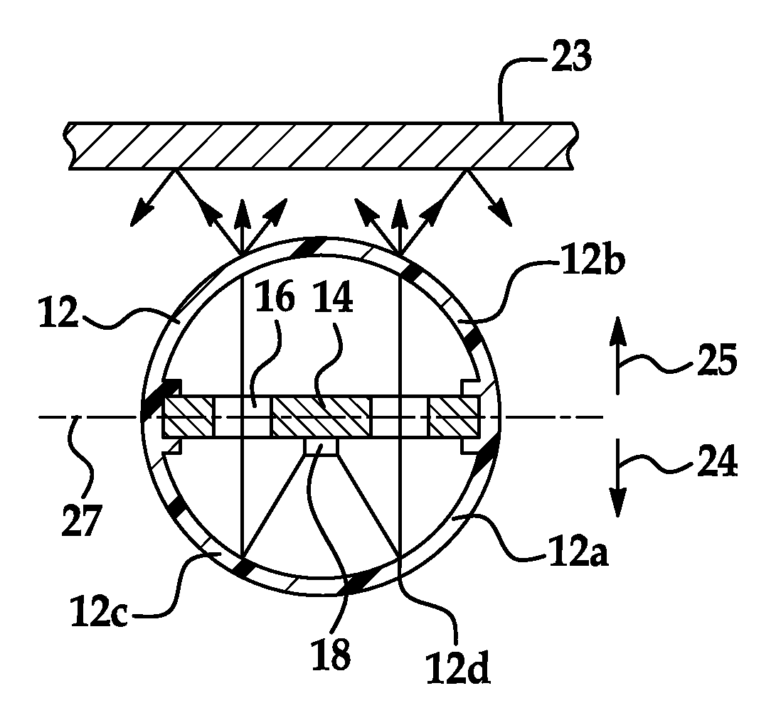
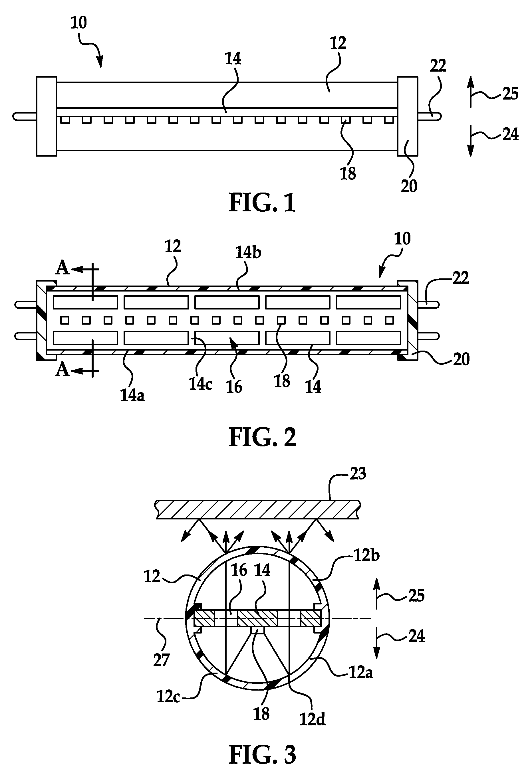
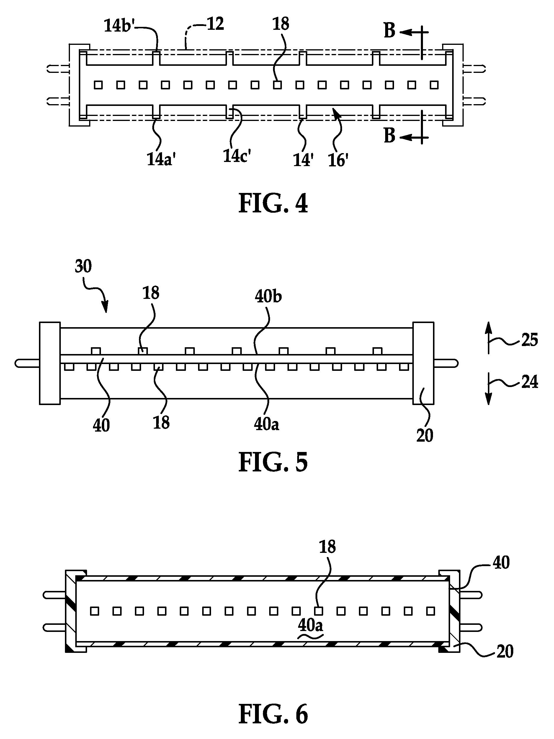
[0022]FIGS. 1-9 illustrate examples of LED-based lights having dual-sided distributions. In the example illustrated in FIGS. 1-3, an LED-based light tube 10 is configured as a replacement for a fluorescent tube in a fluorescent fixture. The light tube 10 includes a housing 12, a circuit board 14 in the housing 12 that defines a plurality of apertures 16, one or more LEDs 18 mounted on the circuit board 14, and a pair of end caps 20 attached at opposing ends of the housing 12. The light tube 10 can additionally include other components, such as electrical components or one or more highly thermally conductive structures for enhancing heat dissipation.

[0023]The housing 12 as shown in FIGS. 1-3 is a light transmitting cylindrical tube. The housing 12 can be made from polycarbonate, acrylic, glass or another light transmitting material. The housing 12 can be transparent or translucent. For example, a translucent housing 12 can be made from a composite, such as polycarbonate with particle...


PUM


Abstract

Disclosed herein are embodiments of LED-based lights for use in fluorescent fixtures that emanate light in a plurality of directions. One embodiment disclosed herein of an LED light for use in a fluorescent light fixture comprises a housing and a circuit board having a first surface configured to face an illumination area, the circuit board mounted in the housing and defining a plane conceptually dividing the housing into a first portion and a second portion. At least one LED is mounted on the first surface of the circuit board and is configured to emanate light in a first direction. Light distribution means is configured to distribute a portion of the light emanated in the first direction to at least a second direction different than the first direction.

Description

CROSS REFERENCE TO RELATED APPLICATIONS[0001]This application claims priority to Provisional Application No. 61 / 317,825 filed Mar. 26, 2010, which is hereby incorporated by reference in its entirety.TECHNICAL FIELD[0002]The invention relates to a light emitting diode (LED) based light tube usable in a fluorescent light fixture in place of a conventional fluorescent tube.BACKGROUND[0003]Fluorescent tubes are widely used in a variety of locations such as schools and office buildings for providing area lighting, for example. A fluorescent tube typically produces an even distribution of light about its circumference. However, the circumferentially uniform light produced by typical fluorescent tubes may be modified after exiting the tube such that the light distribution becomes directional with a greater amount of light directed in a first radial direction compared to a second radial direction.[0004]Consider the example of a fluorescent light fixture installed in a ceiling. The light pro...

Claims


Application Information

Patent Timeline
16 Jun 2015
Publication
US9057493B2
IPC
F21V7/00; F21K99/00; F21V1/00; F21V5/00; F21S4/00; H05K1/02; F21Y101/02; F21Y103/00; F21Y105/00
CPC
F21S4/008; F21K9/17; F21V7/0008; F21V7/0016; F21V7/0025; F21V7/005; F21Y2101/02; F21Y2103/003
Inventors
SIMON, DAVID L.; IVEY, JOHN