Thermal humidifier

a technology of humidifier and humidifier body, which is applied in the direction of lighting and heating apparatus, heating types, domestic applications, etc., can solve the problems of slow steam production speed in this way, and achieve the effects of quick heat of water, rapid absorption and conveying of liquid, and increased indoor humidity

Inactive Publication Date: 2015-06-16
KUO TONG ELECTRICAL TECH HUI ZHOU CO LTD
View PDF14 Cites 2 Cited by
  • Summary
  • Abstract
  • Description
  • Claims
  • Application Information

AI Technical Summary

Benefits of technology

[0005]The objective of this invention is to offer a thermal humidifier provided with a water-absorption member for absorb liquid or water in a water tank. The water-absorption member is disposed around and contact with a PTC heating tube to enable the heating tube to quickly heat the water of the water-absorption member for producing steam to be conveyed into a room for increasing indoor humidity.
[0006]The water-absorption member of the thermal humidifier in the present invention is composed of water-absorption cotton strips, which can quickly absorb and convey liquid or water and are able to cope with the heating velocity of the heating tube, achieving effect of liquid or water atomization.
[0007]The water-absorption member of the thermal humidifier in the present invention has a large portion soaked in the water tank and another part passes around and contacts with the PTC heating tube (a heating tube of positive temperature coefficient) so that the PTC heating tube can quickly atomize liquid or water.

Problems solved by technology

Another conventional method of atomizing liquid, as disclosed in U.S. Pat. No. 8,033,292 and U.S. Pat. No. 8,033,532, is to heat liquid directly to produce steam by a heating element, but the speed of producing steam in this way is slow.

Method used


Image

  • Thermal humidifier
  • Thermal humidifier
  • Thermal humidifier

Examples


Embodiment Construction

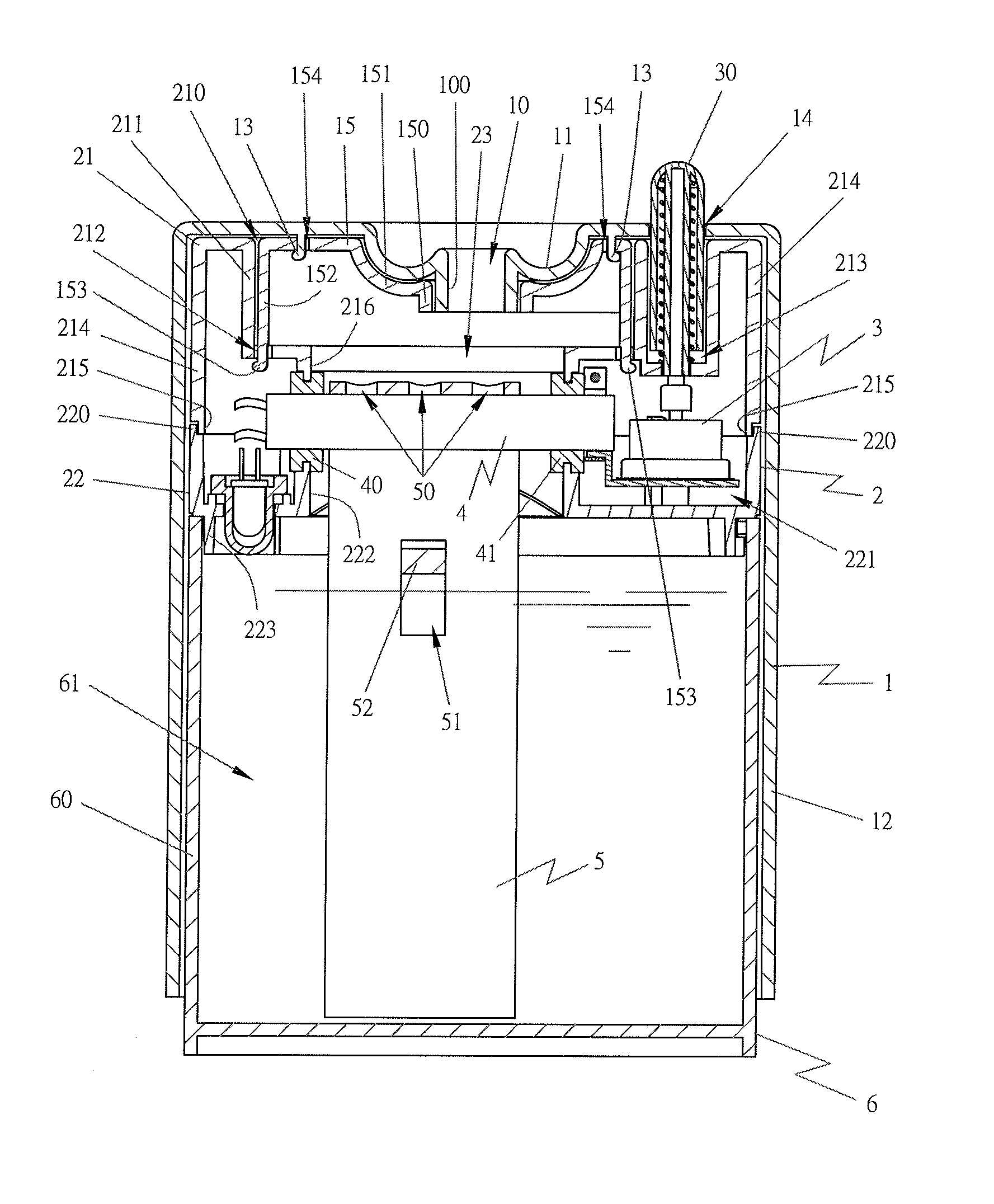
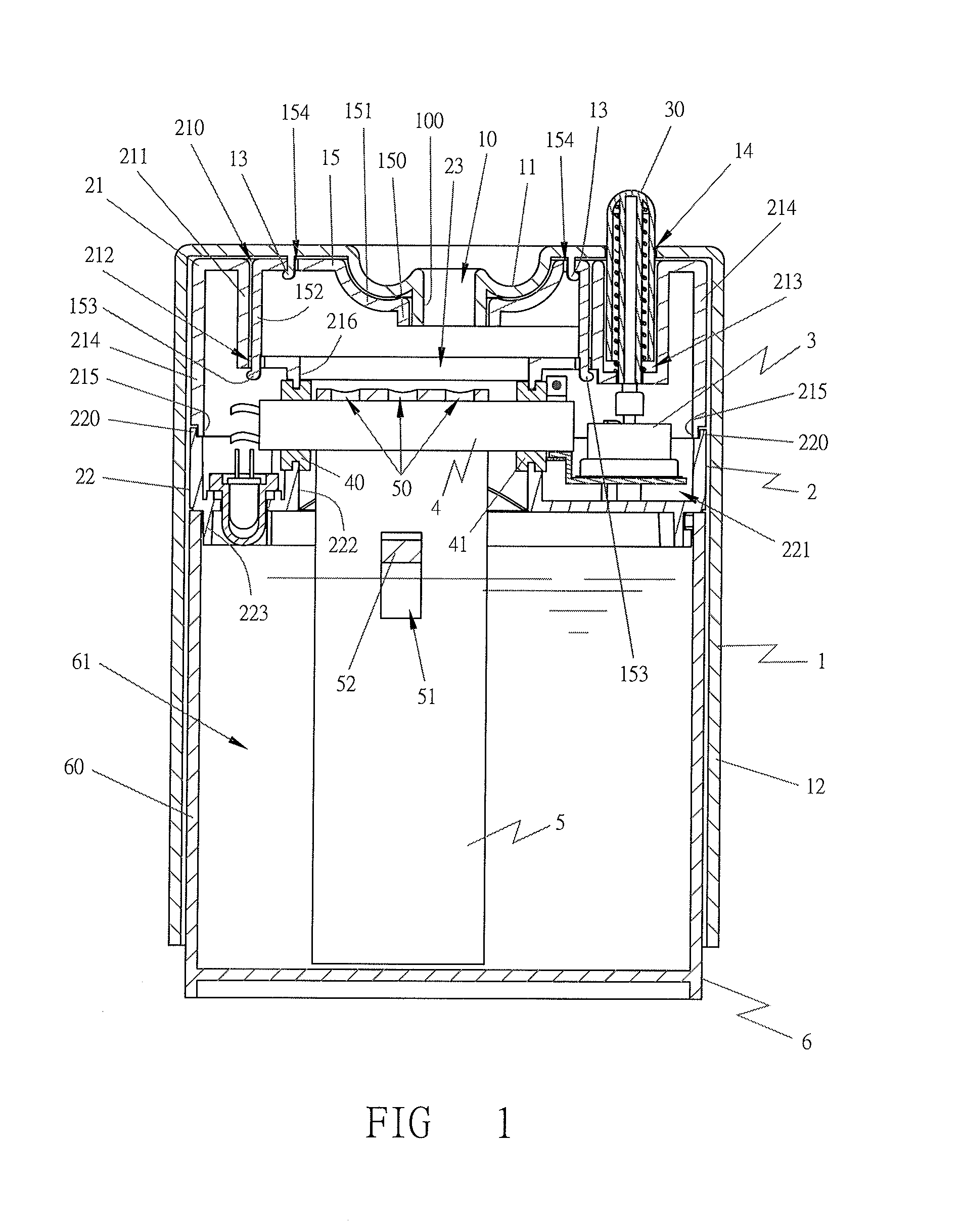
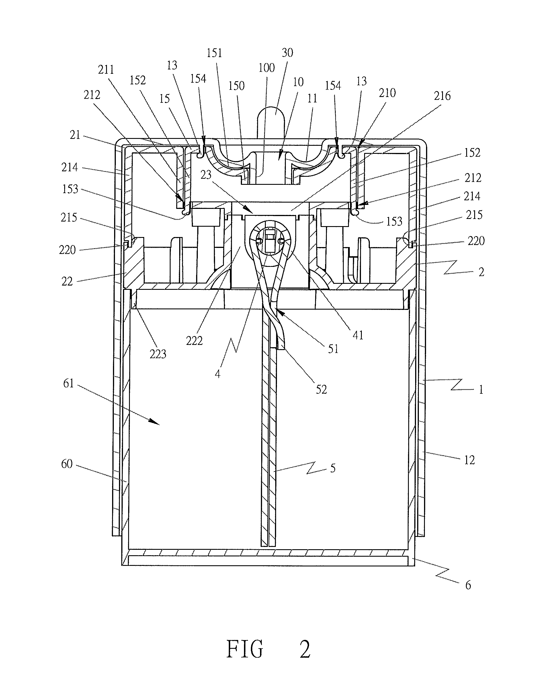
[0013]A preferred embodiment of a thermal humidifier in the present invention, as shown in FIGS. 1 and 2, includes an upper housing 1, a fundamental base 2, a switch or control system 3, a PTC heating tube 4, a water-absorption member 5 and a water box 6 as main components combined together.

[0014]The upper housing 1 is provided with a steam outlet 10 formed with a circumferential side 100 and having its outer circumference formed with a concave face 11, further disposed with a circumferential side 12 extending downward to form an interior that is large enough to receive all the members of the thermal humidifier, as shown in FIGS. 1-3. The upper housing 1 is also provided with combination feet 13 at locations close to the steam outlet 10 to be respectively combined with the combination holes 154 of a steam-collecting member 15 for facilitating assembly and disassembly. Furthermore, the upper housing 1 is bored with an outlet 14 of a temperature-control switch for the temperature-cont...


PUM


Abstract

A thermal humidifier includes an upper housing provided with a steam outlet for conveying steam into a room and combined with a fundamental base having a PTC heating tube installed therein. A water-absorption member is mounted around the PTC heating tube and has a large portion soaked in a water box for absorbing liquid or water from the water box. The water-absorption member, after fully soaking up water, contacts with the PTC heating tube to enable the PTC heating tube to quickly heat the water of the water-absorption member to produce steam to be sent into a room through the steam outlet of the upper housing.

Description

BACKGROUND OF THE INVENTION[0001]1. Field of the Invention[0002]This invention relates to a thermal humidifier, particularly to one employed in a room in areas with comparatively dry climate or in dry seasons. The thermal humidifier of this invention functions to produce steam and convey the steam into a room for increasing indoor humidity after the steam is produced through heating to boil, thus preventing the room from becoming excessively dry or insufficient in humidity and avoiding a person's skin becoming excessively dry and causing itch.[0003]2. Description of the Prior Art[0004]A conventional humidifier generally uses a method of supersonic-wave high-speed oscillation to have water or liquid atomized and converted into atomized liquid through oscillation for over one million times per second and then, the atomized liquid is conveyed into a room by fans for humidifying the room, or uses a method of heating to heat water or liquid to boil for producing steam to be conveyed into...

Claims


Application Information

Patent Timeline
Patent Type & Authority Patents(United States)
IPC IPC(8): F24F6/18F24F6/02
CPCF24F6/18F24F6/025
Inventor HUANG, CHIN-CHENG
Owner KUO TONG ELECTRICAL TECH HUI ZHOU CO LTD
Why Eureka
Try Eureka