Twist and lock glass shade mounting system and method of assembly

Active Publication Date: 2015-06-30
HKC US
View PDF37 Cites 6 Cited by
  • Summary
  • Abstract
  • Description
  • Claims
  • Application Information

AI Technical Summary

Benefits of technology

[0010]A third objective of the present invention is to provide devices, systems and methods for mounting lamp sha

Problems solved by technology

However, these types of popular attachment techniques have several problems.
One problem is the narrow part of the inside of the lamp shade near the narrow neck space makes it difficult to reach with one's fingers.
Holding a nut can be difficult in this narrow space, especially when an installer is reaching upward to remove or install shades onto light socket that are above their heads.
However, the spanner wrench adds an additional cos

Method used


Image

  • Twist and lock glass shade mounting system and method of assembly
  • Twist and lock glass shade mounting system and method of assembly
  • Twist and lock glass shade mounting system and method of assembly

Examples


first embodiment

[0083]FIG. 3 is an exploded enlarged perspective view of the threaded coupler components 100 of the invention. The threaded coupler components 100 can include a threaded insert 110 having an enlarged ring base 112 having an outer diameter slightly smaller than the lamp shade diameter at step edge 16. The threaded insert 110 can have a smaller diameter cylindrical protrusion 114 with exterior threaded surface on one side of the ring base 112, having an internal threaded surface 115. A pair of washers / O-rings 120, 130 such as elastomeric or rubber type washers, can each have a central opening slightly larger than the outer diameter of the cylindrical protrusion 114. A locking ring 140 can include an enlarged ring base 142 and a narrower diameter gripable cylindrical protruding end 144 to one side with an internal threaded surface 145. The threaded insert 110 and the locking ring 140 can be formed from plastic, rubber, composites, metal and the like.

[0084]FIG. 4 is an exploded view of ...

second embodiment

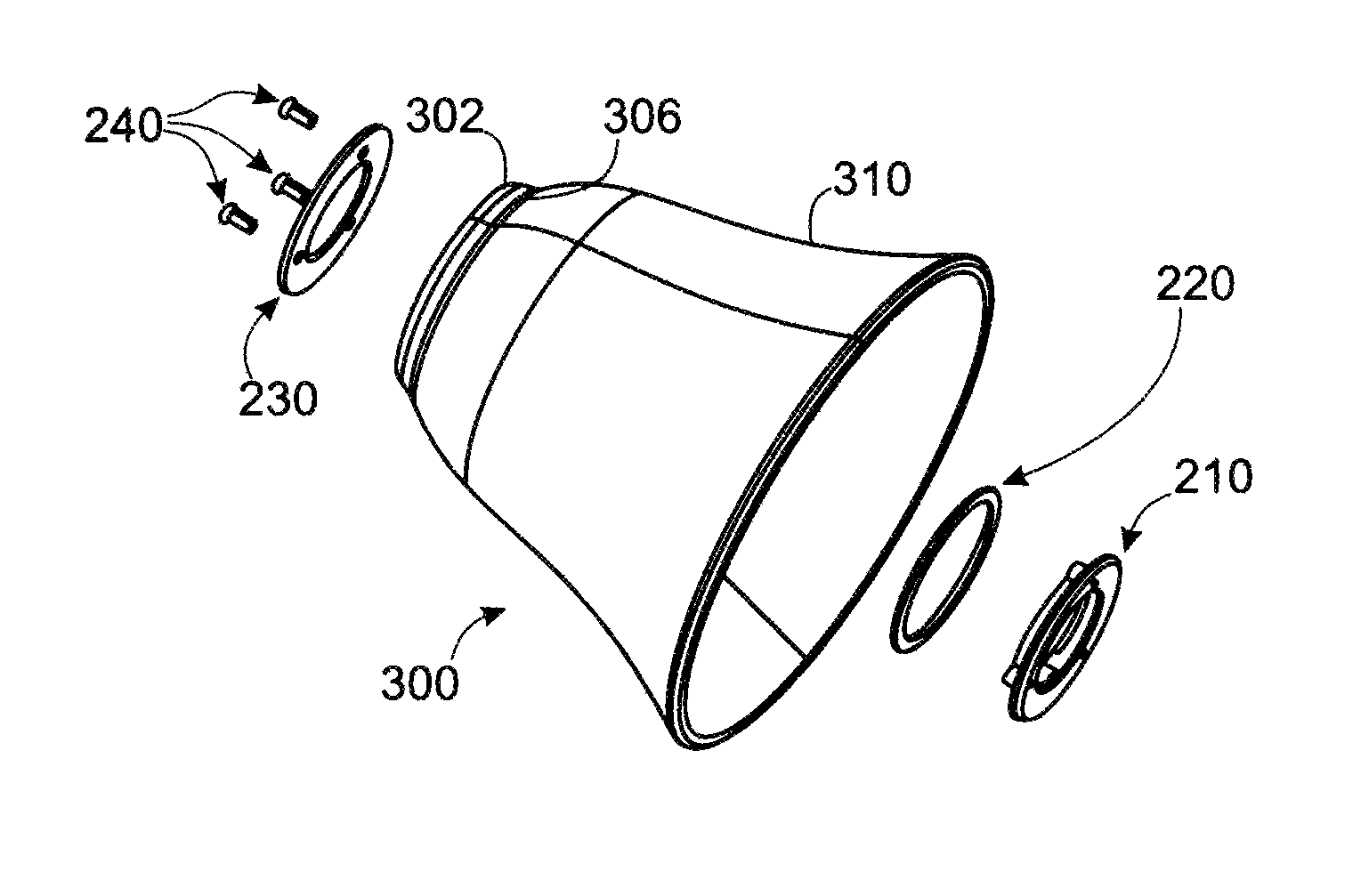
[0092]FIG. 9 is an exploded perspective view of another embodiment of threading adapter coupler components 200 for a lamp shade 300. FIG. 10 is an exploded perspective view of the adapter coupler components 200 of FIG. 9 with a lamp shade 300. FIG. 11 is a perspective view of the threaded adapter coupler components 200 of FIGS. 9-10 mounted to a lamp shade 300. FIG. 12 is an enlarged perspective view of the threaded adapter coupler components 200 mounted to the lamp shade 300 of FIG. 11.

[0093]Referring to FIGS. 9-12, an adapter ring plate 210 has an enlarged base type ring 212 is positioned into the open flared end 310 of lamp shade 300 with edges of the base ring 212 to rest against interior step edge 306 so that narrower diameter raised ring 214 with plural female fastener sockets 215 protrudes through the lamp shade neck 302. Next, the washer / O-ring 220 is positioned against the outside of the narrow lamp shade neck 302. The washer / O-ring 220 can have an outer diameter similar to...


PUM


Abstract

Devices, systems and methods of converting the necks on lamp shades into threadable couplers that allow the shades with the couplers to be screwed onto the exterior threads on light sockets, such as those types of sockets found on wall mounted and ceiling mounted candelabras and ceiling fans. The couplers can include plate members that are fastened in a sandwich configuration on both the inside and outside of the neck portion of the shade with the sandwiched plate members having an interior threaded surfaces. Modified lamp shades can be screwed to exterior threaded light sockets on candelabra lights, pendant lights, ceiling fan lights, and any other type of lamp sockets that have removable lamp shades.

Description

FIELD OF INVENTION[0001]This invention relates to light shade, in particular to devices, systems and methods of converting the necks on lamp shades into threadable couplers that allow the shades with the couplers to be screwed onto the exterior threads on light sockets, such as those types of sockets found on wall mounted and ceiling mounted candelabras and ceiling fans.BACKGROUND AND PRIOR ART[0002]FIG. 1A is an exterior view of a prior art base 1 for a candelabra light fixture. FIG. 1B is a cross-sectional view of the base 1 of FIG. 1A along arrows 1B. FIG. 2A is an exterior view of a prior art lamp shade 10 that can be used with the candelabra light fixture of FIG. 1A. FIG. 2B is a cross-sectional view of the shade 10 of FIG. 2B along arrows 2B.[0003]Referring to FIGS. 1A-2B, a lamp shade 10 having an outwardly flaring out glass 12 with narrow neck 14 are often attached to a candelabra type base 1 by orienting the neck portion 14 over exterior threaded sides 4 of the electrical s...

Claims


Application Information

Patent Timeline
IPC IPC(8): F16B37/02F21V17/06F21V17/10
CPCF21V17/06F21V17/10F21V1/00F21V17/12F21V1/26
Inventor KUYKENDALL, DENNIS C.BURNS, JAMESBYRNE, BRENDANNEMEC, BRUCE C.ROHR, JASON
Owner HKC US
Why Eureka
Try Eureka