Swirl entraining range hood with separatedly installed core mechanism and smoke collecting cover
A technology for rolling a range hood and a fume collecting hood is applied in the field of pneumatic dust removal devices, and can solve the problems of increased load, frequent replacement of range hoods, sticking of valve plates, etc.
- Summary
- Abstract
- Description
- Claims
- Application Information
AI Technical Summary
Problems solved by technology
Method used
Image
Examples
Embodiment 1
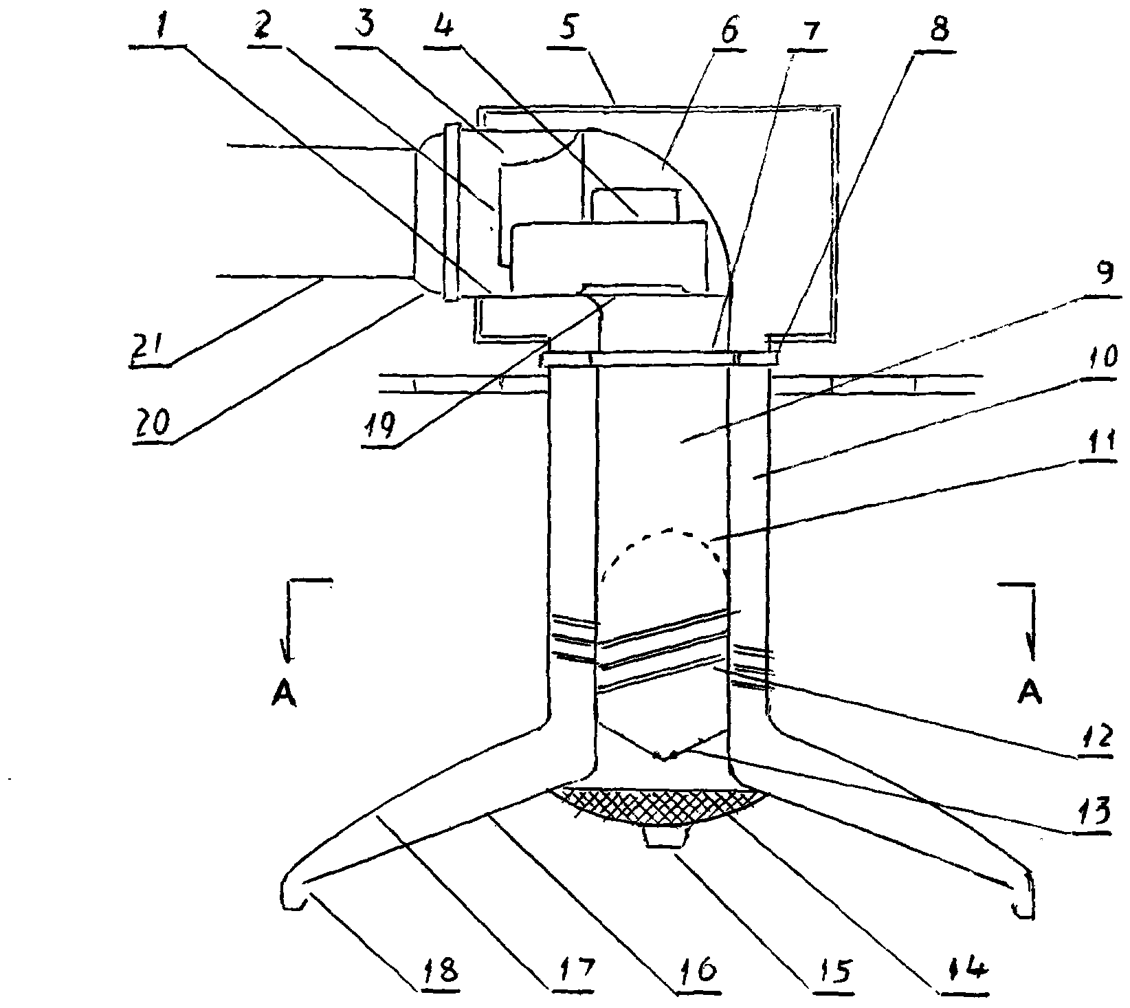
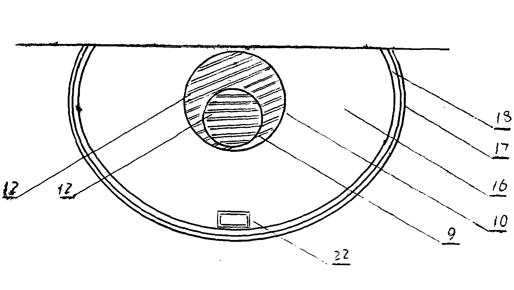
[0028] This embodiment is the embodiment that the present invention uses a circular smoking pipe instead of a square hoisting tube to suspend a rugby surface-shaped fume collecting hood.
[0029] Such as figure 1 , figure 2 Shown in: a horn 2 is embedded concentrically at one end of a section straight circular tube 1 with a diameter of 200mm, the generatrix of the horn 2 is parabolic, and the diameter of the small mouth of the horn 2 is 0.6 to 0.6 to the diameter of its large mouth. 0.8 times, the length of the horn is 0.6 to 0.8 times the length of the straight tube, the diameter of the large mouth of the horn is equal to the diameter of the tube, and a circular groove with a "V" shape in cross section and a closed bottom is formed at one end of the straight tube 3. A centrifugal fan 4 is installed on the outside of the annular groove 3. The air supply pipe of the fan is connected tangentially to the annular groove 3 and leads to the middle of the annular swirl groove 3; th...
Embodiment 2
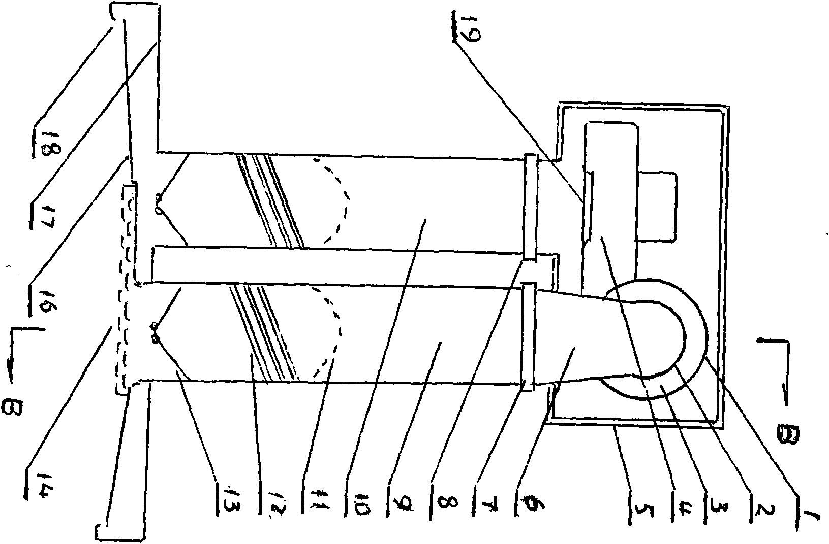
[0032] This embodiment is the embodiment of the present invention in which an ultra-thin European-style smoke collecting hood is suspended by two thin round tubes on a domestic general-purpose double-cooker cooktop.
[0033] Such as image 3 , Figure 4 , shown in: In the present embodiment, in a sealed sound-absorbing square box 5, a horizontally installed swirl entrainment device, and one end of the swirl entrainment device is sealed and protruded from one side of the square box 5 as a smoke exhaust pipe. Joint 20, the structure and installation mode of these several parts, fittings are identical with embodiment 1. What is different from Embodiment 1 is that: for the domestic general-purpose two stove tops, the reducing elbow 6 installed at the bottom of the annular groove at one end of the straight tube 1 is sealed downward from the bottom surface of the square box 5. Go out towards the cooktop, make the joint 7 of the swirl oil smoke pipe, choose a metal colored surface ...
Embodiment 3
[0036] The present embodiment is an implementation example of the utility model on an island-type stove top, with three round pipes hanging a plum-blossom-shaped fume-collecting hood in the air.
[0037] Such as Figure 4 , Figure 5 As shown in ,: the swirl entrainment device in this embodiment is erected in the sound-absorbing and sealed square box 5, and extends into a horn 2 concentrically from the lower end of a section of straight circular pipe 1 to form a cross-section An annular groove 3 with a closed bottom in a "V" shape, two centrifugal fans 4 of the same type are installed on both sides of the annular groove, and the two fans are juxtaposed with the annular groove 3 in the shape of a "product". The air supply pipe enters the annular groove 3 symmetrically and tangentially, and installs a straight pipe variable diameter pipe 6 at the bottom of the annular groove 3 as the joint 7 of the swirl entrainment smoke pipe, and installs the joint of the smoke exhaust pipe a...
PUM
 Abstract
Description
Claims
Application Information
 - R&D
- Intellectual Property
- Life Sciences
- Materials
- Tech Scout
- Unparalleled Data Quality
- Higher Quality Content
- 60% Fewer Hallucinations
Browse by: Latest US Patents, China's latest patents, Technical Efficacy Thesaurus, Application Domain, Technology Topic, Popular Technical Reports.
© 2025 PatSnap. All rights reserved.Legal|Privacy policy|Modern Slavery Act Transparency Statement|Sitemap|About US| Contact US: help@patsnap.com


