Arrangements, braces, and methods for supporting an arm of an ornamental fixture

a technology for supporting arms and ornamental fixtures, which is applied in the direction of lighting support devices, washstands, applications, etc., can solve the problems of limiting the size of glass components, affecting the design of ornamental fixtures, and affecting the appearance of ornamental fixtures

Active Publication Date: 2005-08-11
W SCHONBEK LLC
View PDF24 Cites 6 Cited by
  • Summary
  • Abstract
  • Description
  • Claims
  • Application Information

AI Technical Summary

Benefits of technology

[0011] Thus, aspects of the present invention provide for improved braces, mounting arrangements, and methods for mounting arms for ornamental fixtures, for example, for supporting glass arms for ornamental lighting fixtures. In addition, aspects of the present invention provide improved means of mounting ornaments, for example, means of mounting ornaments to glass arm assemblies where the load of the ornaments is not imposed upon the glass arm.

Problems solved by technology

The design of ornamental fixtures, such as chandeliers, is typically hampered by the disadvantages of using glass as the material of construction.
In contrast to other materials of construction, glass is typically more brittle and more prone to fracture due to its lower tensile strength.
Typically, in the conventional art, the lower strength of glass limits the size of glass components and the loading of chandeliers, for example, limits the size and number of ornaments that can be attached to glass components of chandeliers.
The fragility of such glass arms typically limits the size, for example, the length, and the carrying capacity of such arms.
Also, typically, the size and number of ornaments that can be hung from such glass arms are limited.
As a result, the limitations of the carrying capacity of glass arms limits or compromises the freedom designers have in designing glass arm chandeliers.
The limitations of conventional glass arm chandelier design are particularly acute as the size of the chandelier increases.
Ever increasing customer demands for larger and more elaborate chandeliers further underscore the limitations of conventional glass arm design.

Method used


Image

  • Arrangements, braces, and methods for supporting an arm of an ornamental fixture
  • Arrangements, braces, and methods for supporting an arm of an ornamental fixture
  • Arrangements, braces, and methods for supporting an arm of an ornamental fixture

Examples


Embodiment Construction

[0026] The details and scope of the aspects of the present invention can best be understood upon review of the attached figures and their following descriptions.

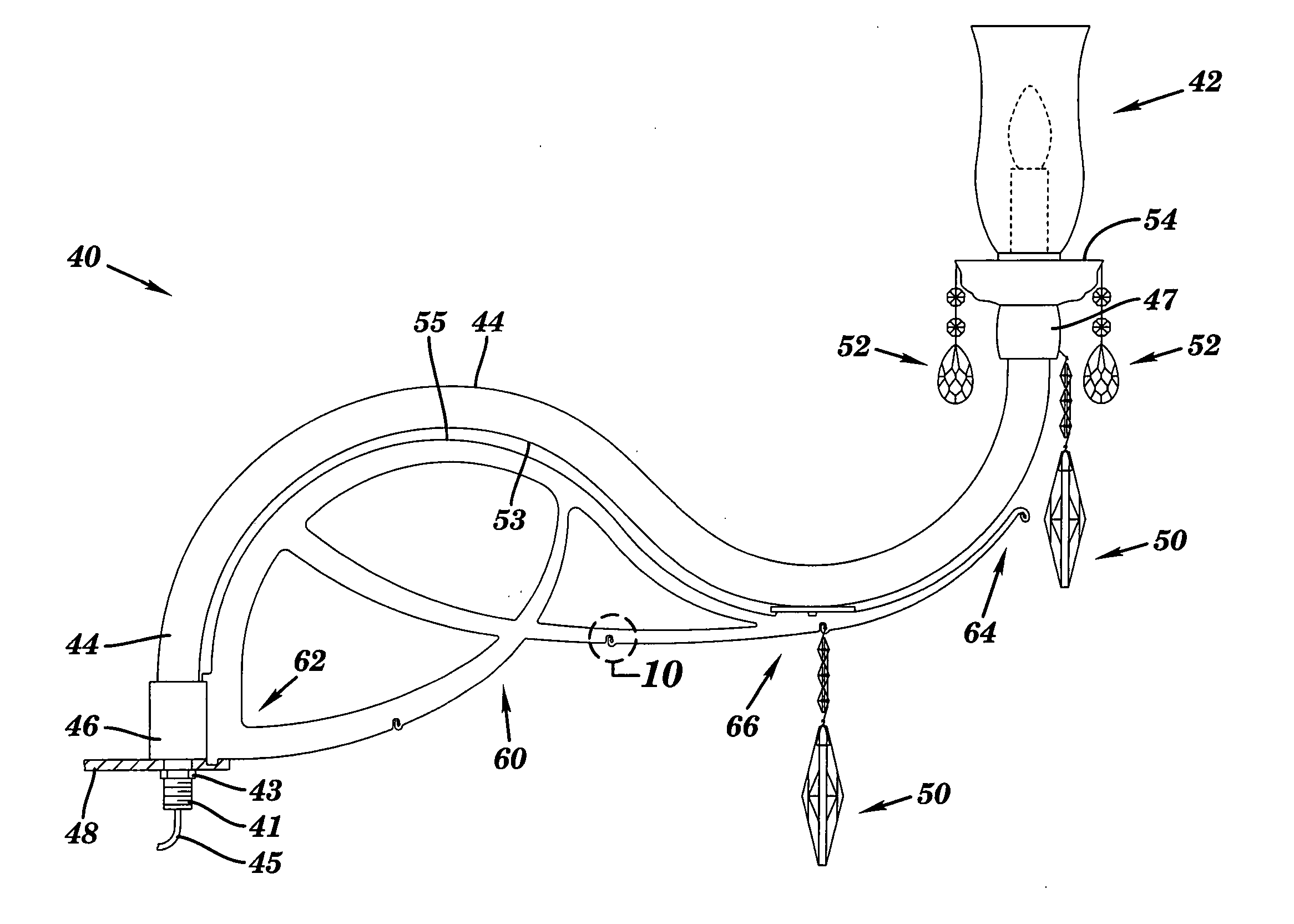
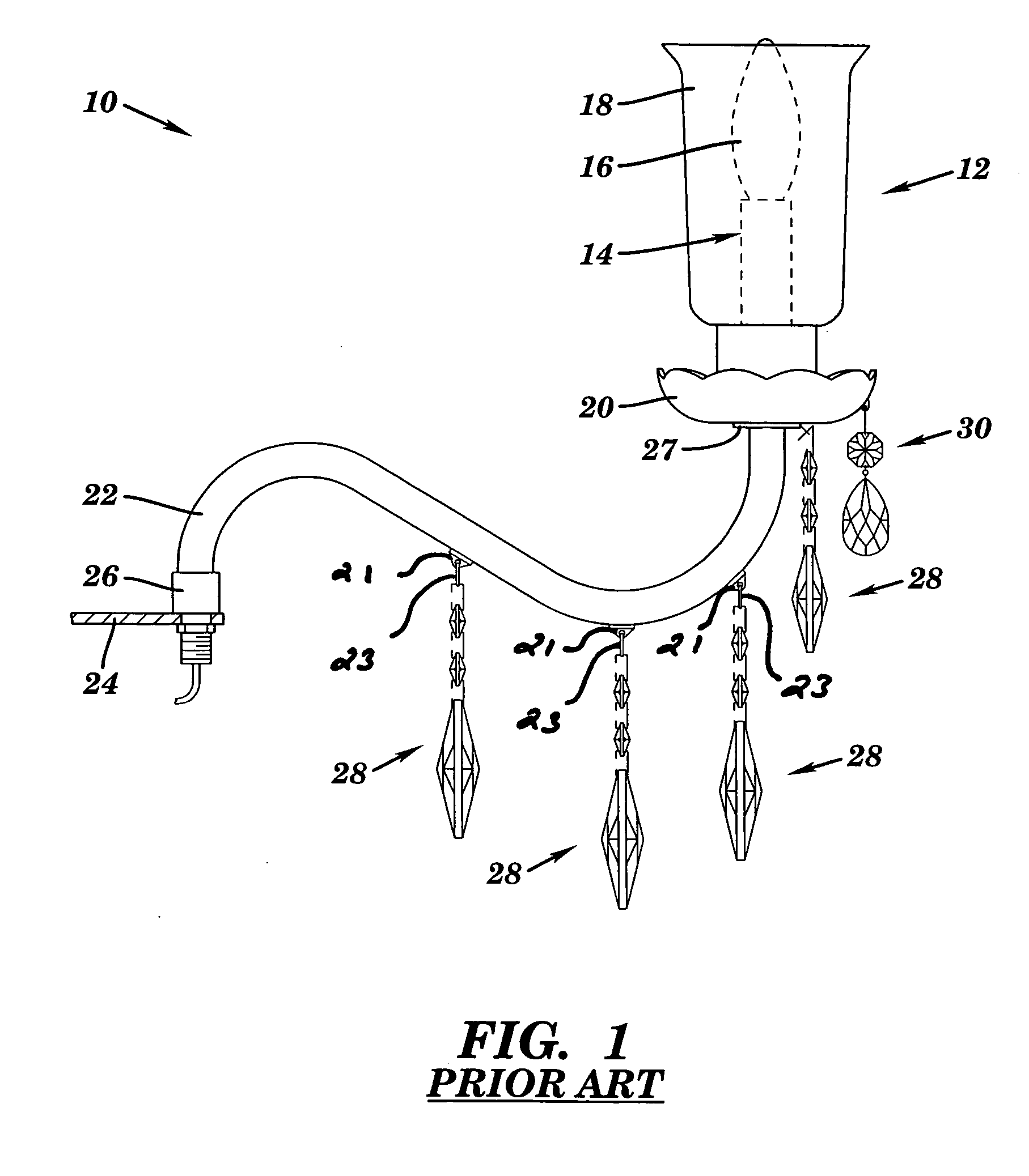
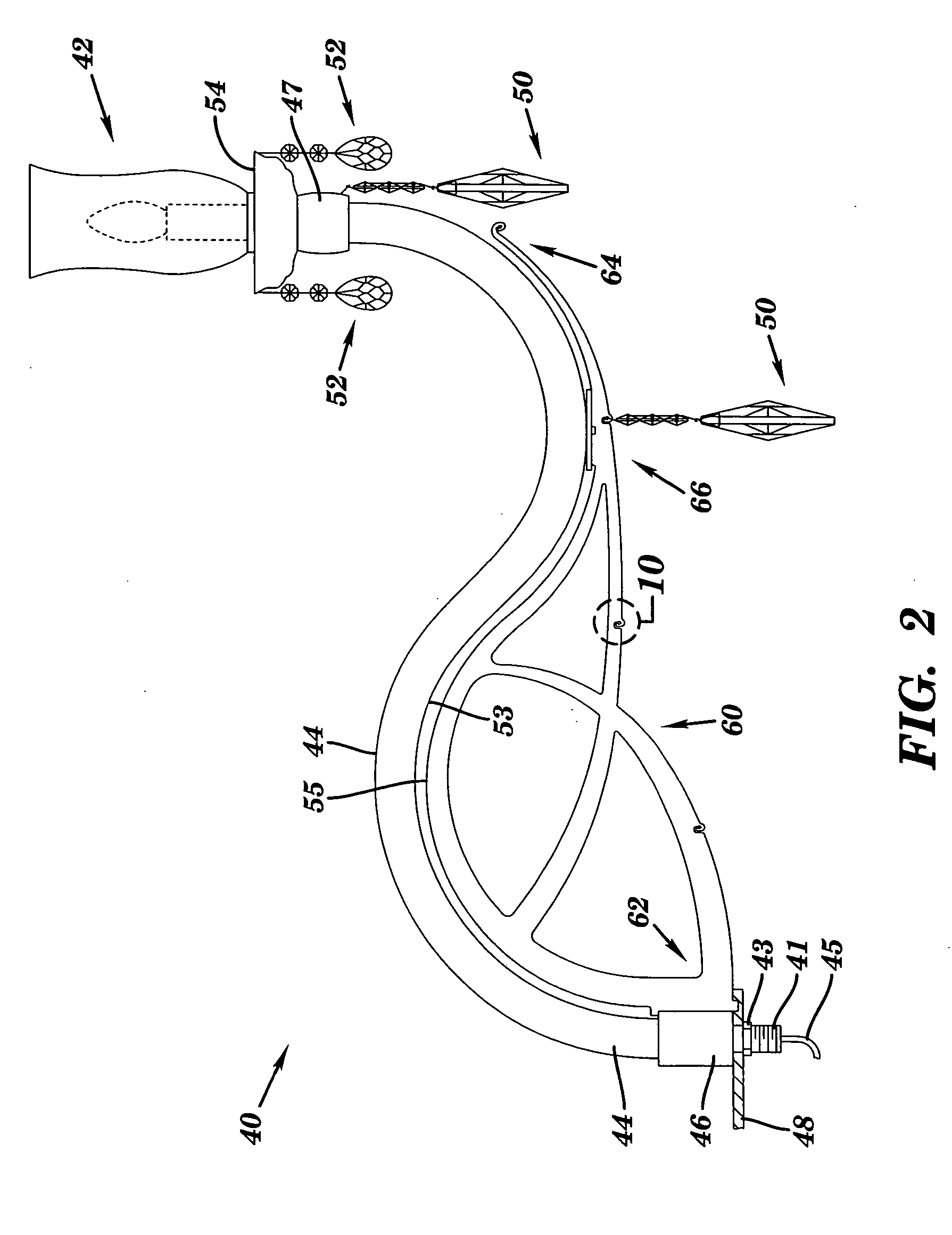
[0027]FIG. 1 is a side elevation view of prior art fixture mounting 10 over which the present invention is an improvement. Fixture mounting 10 supports a fixture 12. In the prior art mounting shown in FIG. 1, fixture 12 includes a light fixture 14 having a bulb 16 which is enclosed within a glass shade 18, in this case, a hurricane glass shade. In this prior art arrangement, fixture 12 also includes a decorative crystal bobeche 20. Fixture 12 is supported on a glass arm 22, in this case, a curved glass arm, which is mounted to a mounting plate 24 by conventional means. As is typical in the art, arm 22 may have ferrules 26, 27 mounted at either end of arm 22 to function as interfacing structures between arm 22 and support plate 24 and arm 22 and fixture 12, respectively. As is also typical in the art, numerous decorative orn...


PUM


Abstract

Arrangements, braces, and methods for supporting an arm of an ornamental fixture, for example, chandeliers, are provided. The arrangements and braces include elongated elements having first ends adapted to be mounted to a support, a second free end, and a platform located between the first end and the second end for supporting the arm of the fixture. Aspects of the invention may be used to support fragile arms of chandeliers, for example, glass arms. Aspects of the invention allow for the use of longer arms, for example, for use in chandeliers over 10 feet in diameter, or for arms having higher loadings, for example, having heavier or more numerous ornaments and light fixtures.

Description

CROSS REFERENCE TO RELATED APPLICATIONS [0001] This application is related to the following application which is commonly-assigned and filed at the same time as this application: [0002] Utility patent application entitled “ARRANGEMENTS AND METHODS FOR CONNECTING DECORATIVE ORNAMENTS” filed on ______ and having Ser. No. ______ [Attorney Ref. 2350.422]. This application is incorporated by reference herein in its entirety.FIELD OF THE INVENTION [0003] This invention relates, generally, to braces, arrangements, and methods for supporting arms of ornamental fixtures, for example, lamps and chandeliers, more particularly, to braces, arrangements, and methods for supporting glass arms of decorative fixtures. BACKGROUND OF THE INVENTION [0004] The design of ornamental fixtures, such as chandeliers, is typically hampered by the disadvantages of using glass as the material of construction. In contrast to other materials of construction, glass is typically more brittle and more prone to fract...

Claims


Application Information

Patent Timeline
Patent Type & Authority Applications(United States)
IPC IPC(8): F21S8/06F21V5/06F21V21/02F21V21/108F21V21/116
CPCF21S8/065F21V5/06F21V21/116F21V21/108F21V21/02
Inventor BAYER, GEORGESCHONBEK, ANDREW J.TUCKER, DANIEL
Owner W SCHONBEK LLC
Why Eureka
Try Eureka