
Hand carrier for a long arm firearm

a long-arm firearm and hand carrier technology, applied in the field of easy, less fatiguing carrying of a long-arm firearm, can solve the problems of not being available, not allowing quick access to the firearm in a combat or hunting situation, and additionally cumbersome manipulation

Inactive Publication Date: 2006-05-16
FRS VIRGIL P
View PDF13 Cites 11 Cited by
  • Summary
  • Abstract
  • Description
  • Claims
  • Application Information

AI Technical Summary

Benefits of technology

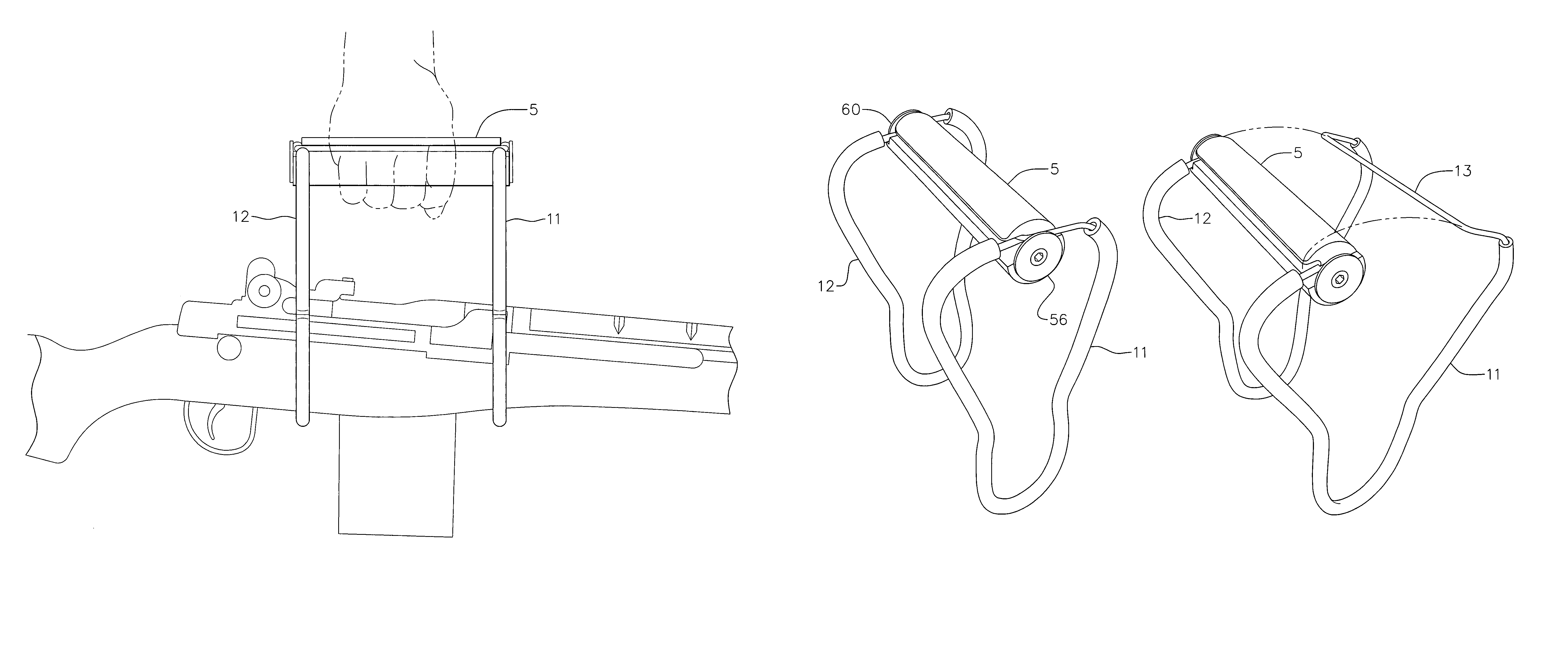
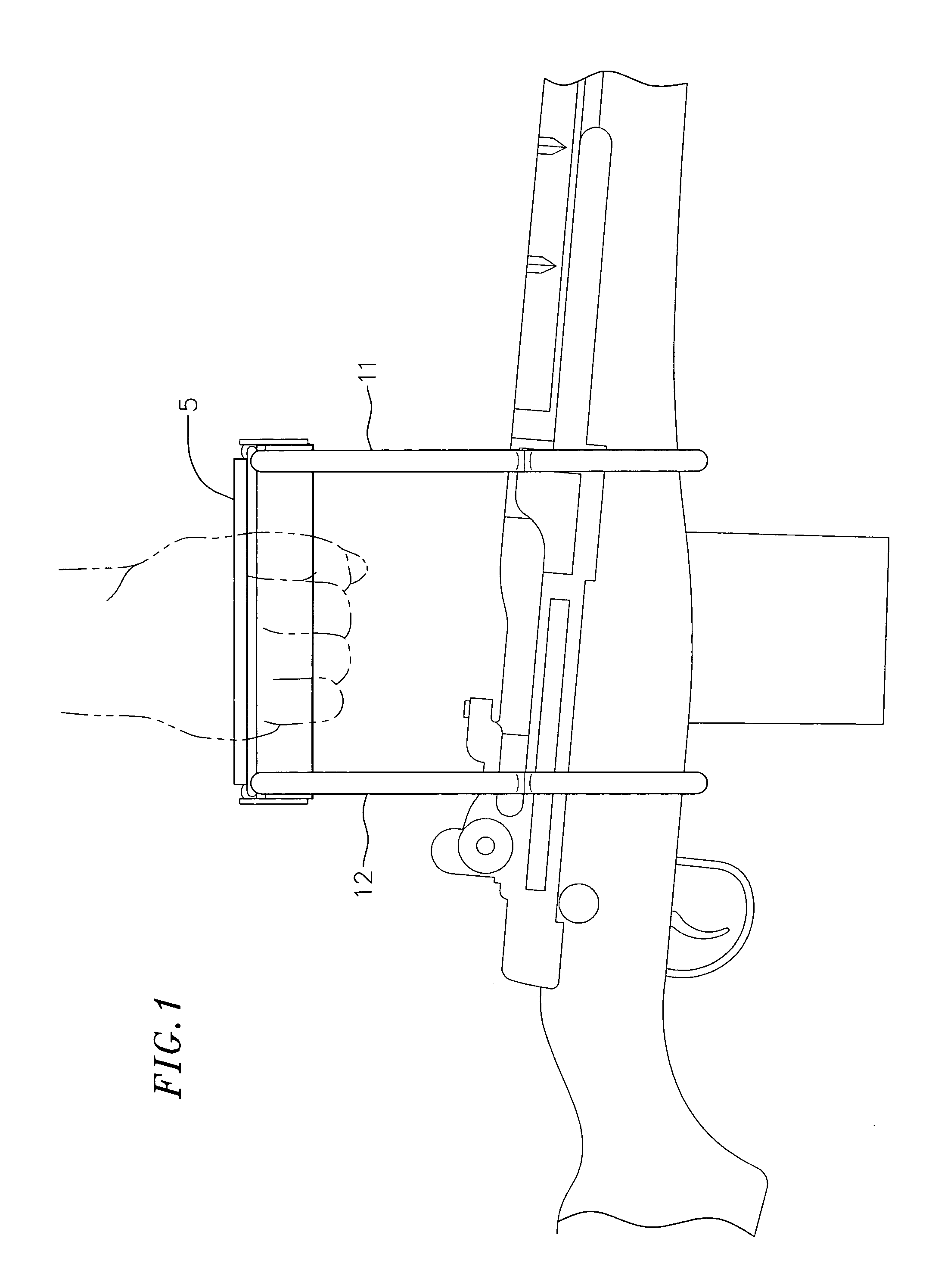
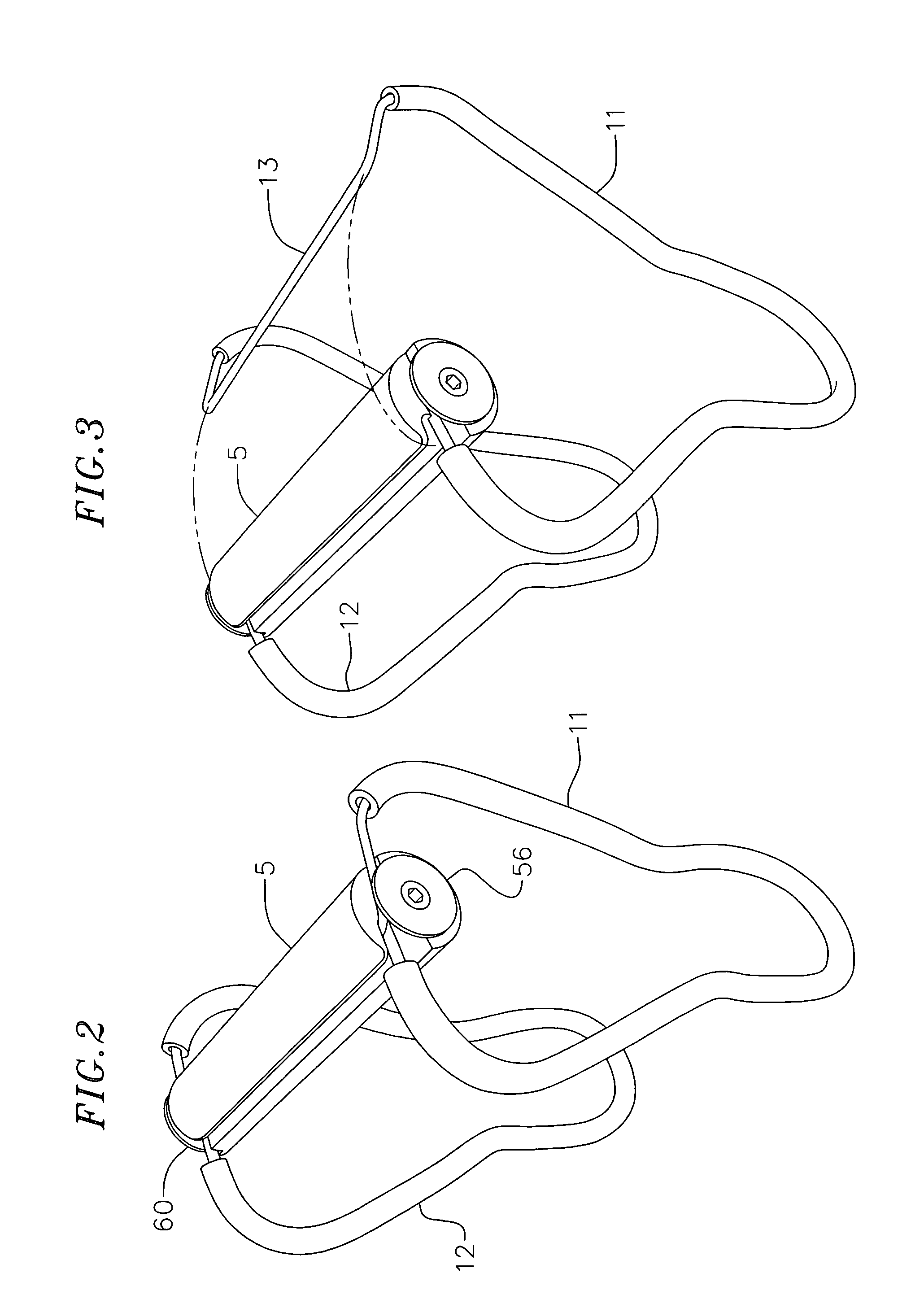
[0011]In accordance with the present invention, a hand carrier for a long arm firearm comprises an elongated, cylindrical handle attached to a grasping cradle. The handle is made of one piece of hard material grooved and drilled to permit releasable attachment to the grasping cradle. The grasping cradle has a front and back section, both of which are U-shaped at the bottom to securely hold the long arm firearm. These sections are joined to a straight-line section and open section in forming the cradle. The front and back members have a right and left side that are essentially symmetrical about a centerline through the U at the bottom and middle of the cross-section of the handle at the top. In the closed position, the only visible deviation in symmetry is the greater height of the right side of the front and back members. This greater height allows the overlap of the straight-line right side section over the open left side section.
[0013]In addition, the front and back members of the cradle are covered by protective sleeves of rubber, plastic or other materials. These sleeves may be easily replaced.
[0014]The design of the hand carrier of this invention results in a carrier that is tight in weight and easily repaired. Further the operation is improved and there is no pinching of fingers when the carrier is being attached to a long arm firearm or being removed therefrom.

Problems solved by technology

The conventional sling, although permitting the firearm bearer to do other things with his hands, does not permit access to the firearm quickly in a combat or hunting situation.
In the event that the firearm must be aimed and discharged quickly, both of the above-described carrying positions require time to reorient the firearm, time which may not be available.
These manipulations are made additionally cumbersome when the bearer is wearing thick or heavy clothing or is restricted in his movement by his surroundings.
Also, the barrel of the firearm being carried, unless extremely short, tends to catch on vegetation and other impediments to travel, causing undue crouching and maneuvering by the bearer.
In addition, contact with any impediment creates unwanted sound.
Another problem with conventional slings is that they normally must be adjusted to fit both the firearm and the bearer, thus precluding rapid change in use to another firearm or use by another bearer.
However, the unaided across-the-chest carry and the unaided one-hand carry are very fatiguing.
However, it has been found that the design suffers from several disadvantages.
The cradle, having a front member and a back member that are permanently attached to the handle, cannot be easily repaired.
If the handle is made of wood, considerable loss will occur during production of the handle pieces because of irregularities and defects in lumber stock and difficulty in machining to the necessary tolerances of the design.
If molded from plastic material or other material, the cost of the handle increases.
Although, not evident from the patent, it has been found that the attaching and detaching of the carrier of the design shown in the patent requires considerable practice to avoid pinching of the fingers.

Method used


Image

  • Hand carrier for a long arm firearm
  • Hand carrier for a long arm firearm
  • Hand carrier for a long arm firearm

Examples


Embodiment Construction

[0025]For purposes of describing the invention. a rifle will be used as the long arm firearm to be carried. Also with reference to the drawings, particularly FIG. 1 thereof, the end of the carrier nearer the barrel of the rifle is designated for purposes of illustration and description the front of the carrier. The end of the carrier nearer to the stock of the rifle is the back of the carrier.

[0026]The bottom of the carrier is U-shaped and is configured to cradle and to hold a rifle. The top of the carrier has a handle for carrying a rifle in the carrier. When in use, the carrier is in a closed position, as shown in FIGS. 1, 2, 4 and 9. To remove a rifle or to insert a rifle the carrier is in an open position, as shown in FIGS. 3 and 5. The carrier is held in the open position by the spring action of the wire body or frame of the carrier. To place the carrier in the closed position, one side of the carrier is forced toward the other side of the carrier and locked into the closed pos...


PUM


Abstract

A hand carrier for long arm firearms having a handle and a single strand of wire bent to form two saddles to grip and support the firearm with an open section of the wire detachably attached to the handle and a straight-line of the wire being held in the handle for a closed carrying position and removed from the handle for an open position for inserting or removing the firearm.

Description

BACKGROUND OF THE INVENTION[0001]1) Field of the Invention[0002]This invention relates to the easy, less fatiguing carrying of a long arm firearm (rifle, shotgun, or muzzle loader), and, more particularly, to an easy-to-use carrier having two cooperating members for cradling and securely holding a long arm firearm and a handle for holding the carrier.[0003]2) Related Art[0004]Slings have been employed with hand-carried firearms by both hunters and military personnel for many years. The purpose of such devices is to relieve the bearer from the burden of carrying the long arm firearm (normally a rifle) with his arms except during those periods of time in which it is anticipated that the firearm will be used, or is actually being used. The conventional sling, although permitting the firearm bearer to do other things with his hands, does not permit access to the firearm quickly in a combat or hunting situation. Thus, the conventional sling, a flexible strap connected at the forward end ...

Claims


Application Information

Patent Timeline
Patent Type & Authority Patents(United States)
IPC IPC(8): F41A23/00F41C33/08
CPCF41C33/08
Inventor FRANKS, VIRGIL P.
Owner FRS VIRGIL P
Learn More