Retractable treatment instrument for endoscope

a treatment instrument and endoscope technology, applied in the field of retractable treatment instruments, can solve the problems of operator's inability to perform endoscopic treatment as intended, the length of the front-end treatment member from the tip of the flexible sheath cannot be kept constant, and the front-end treatment member may be forced to rota

Inactive Publication Date: 2010-07-06
HOYA CORP
View PDF33 Cites 98 Cited by
  • Summary
  • Abstract
  • Description
  • Claims
  • Application Information

AI Technical Summary

Benefits of technology

[0006]The present invention is advantageous in that it provides a retractable treatment instrument configured such that the protruding length from a tip of a flexible sheath can be adjusted at desired lengths so that an endoscopic treatment can be performed as desired by an operator.
[0008]With this configuration, it is possible to securely hold the front-end treatment member at a desirable position while setting the protruding length of the front-end treatment member from the tip of the flexible sheath at a desired length.

Problems solved by technology

However, a conventional treatment instrument disclosed in the publication has a drawback that the protruding length of the front-end treatment member from a tip of the flexible sheath can not be kept constant at states other than a state where the front-end treatment member is protruded at the maximum from the tip of the flexible sheath and a state where the front-end treatment member is fully retracted into a tip portion of the flexible sheath.
The conventional treatment instrument has another drawback that the front-end treatment member may be forced to rotate at the tip portion of the flexible sheath about an axis thereof if the front-end treatment member is pressed against a mucous membrane.
Therefore, there may be a case where an operator can not perform an endoscopic treatment as intended.

Method used


Image

  • Retractable treatment instrument for endoscope
  • Retractable treatment instrument for endoscope
  • Retractable treatment instrument for endoscope

Examples


first embodiment

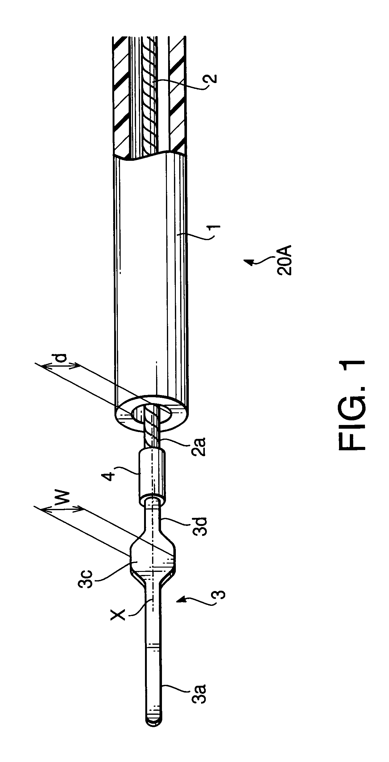
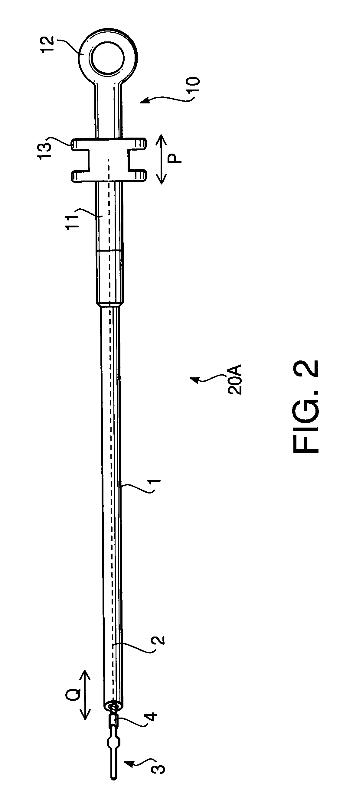
[0056]FIG. 2 is a general view of a retractable treatment instrument 20A for endoscopes according to a first embodiment of the invention. The retractable treatment instrument 20A includes a flexible sheath 1 formed of an insulative flexible tube such as a tetrafluoroethylene resin tube. A conductive operation wire 2 is disposed in the inside of the flexible sheath 1 along the length of the flexible sheath 1 so that the operation wire 2 is movable along an axial direction of the operation wire 2. The flexible sheath 1 may be configured such that at least a tip portion thereof is formed of a flexible tube.

[0057]A front-end treatment member 3 (for example, formed of a stainless steel plate) is connected to a tip of the operation wire 2 via a connection pipe 4 (for example, formed of a stainless steel pipe) so that the front-end treatment member 3 is retractable with respect to the tip of the flexible sheath 1. That is, the front-end treatment member 3 moves forward or backward with res...

second embodiment

[0069]FIG. 7 is an enlarged view of a tip portion of a retractable treatment instrument 20B for endoscopes according to a second embodiment of the invention. FIG. 8 is a general view of the retractable treatment instrument 20B according to the second embodiment. In FIGS. 7 and 8 (and in the other drawings of the second embodiment), to elements which are similar to those of the first embodiment, the same reference numbers are assigned, and the detailed description thereof will not be repeated.

[0070]One of the features of the retractable treatment instrument 20B according to the second embodiment is that a paddle 3b is formed at a tip of the rod-like part 3a of the front-end treatment member 3. The paddle 3b is configured to have a width W1 which is substantially equal to the width W of the wide part 3c or smaller than the width W to some extent.

[0071]As shown in FIG. 8, a connector 14 to which a high-frequency power source cable can be connected is located on the movable hook 13 of t...

third embodiment

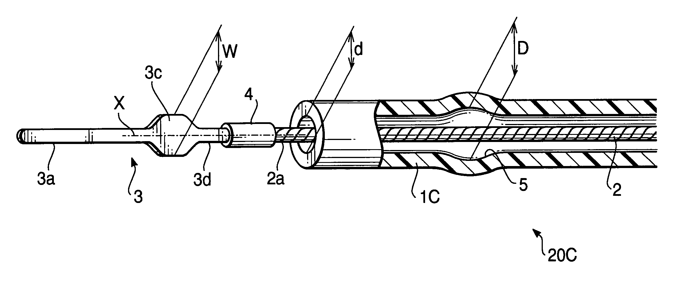
[0081]FIG. 17 is an enlarged view of a tip portion of a retractable treatment instrument 20C for endoscopes according to a third embodiment of the invention. FIG. 18 is a general view of the retractable treatment instrument 20C according to the third embodiment. In FIGS. 17 and 18 (and in the other drawings of the third embodiment), to elements which are similar to those of the first and second embodiments, the same reference numbers are assigned, and the detailed description thereof will not be repeated.

[0082]Similarly to the second embodiment, the retractable treatment instrument 20C is provided with the connector 14 to which a high-frequency power source cable is connected. Therefore, the retractable treatment instrument 20C is used as a high-frequency incision instrument. If the retractable treatment instrument 20C is used as a mechanical incision instrument, it is not necessary to connect the high-frequency power source cable to the connector 14.

[0083]If the operation wire 2 is...


PUM


Abstract

A retractable treatment instrument for an endoscope is provided. The retractable treatment instrument includes a flexible sheath configured such that at least a tip portion thereof is formed of a flexible tube, an operation wire inserted in the flexible sheath so as to be movable along an axial direction of the operation wire in the flexible sheath, and a front-end treatment member attached to a tip of the operation wire. In this structure, the front-end treatment member is movable back and forth along the axial direction with respect to a tip of the flexible sheath. The front-end treatment member has a wide part elongated in a radial direction of the flexible tube to press and broaden the flexible tube from an inside of the flexible tube.

Description

BACKGROUND OF THE INVENTION[0001]The present invention relates to a retractable treatment instrument to be inserted into an instrument-inserting channel of an endoscope.[0002]There are a large number of types of treatment instruments for endoscopes. For example, Japanese Patent Provisional Publication Number HEI 8-299355 discloses one of such treatment instruments for endoscopes. The treatment instrument disclosed in the publication includes a front-end treatment member connected to a leading end of an operation wire inserted into a flexible sheath to be movable along an axial direction of the flexible sheath. The treatment instrument is used, for example, as a high-frequency incision instrument.SUMMARY OF THE INVENTION[0003]However, a conventional treatment instrument disclosed in the publication has a drawback that the protruding length of the front-end treatment member from a tip of the flexible sheath can not be kept constant at states other than a state where the front-end trea...

Claims


Application Information

Patent Timeline
Patent Type & Authority Patents(United States)
IPC IPC(8): A61B1/00A61B17/00A61B17/22A61B17/28A61B17/32A61B18/12A61B18/14
CPCA61B17/22031A61B17/221A61B17/32A61B17/320016A61B18/1492A61B2017/00269A61B2017/22049A61B2017/2946A61B2018/1407A61B2018/1422A61B2018/1475
Inventor OUCHI, TERUO
Owner HOYA CORP
Why Eureka
Try Eureka