

Fuel cell
a fuel cell and fuel cell technology, applied in the field of fuel cells, can solve the problems that the desired power generation performance cannot be maintained, and achieve the effect of preventing the shortcut of reactant gases, simple structure, and desired power generation performan
- Summary
- Abstract
- Description
- Claims
- Application Information
AI Technical Summary
Benefits of technology
Problems solved by technology
Method used
Image

Examples
first embodiment
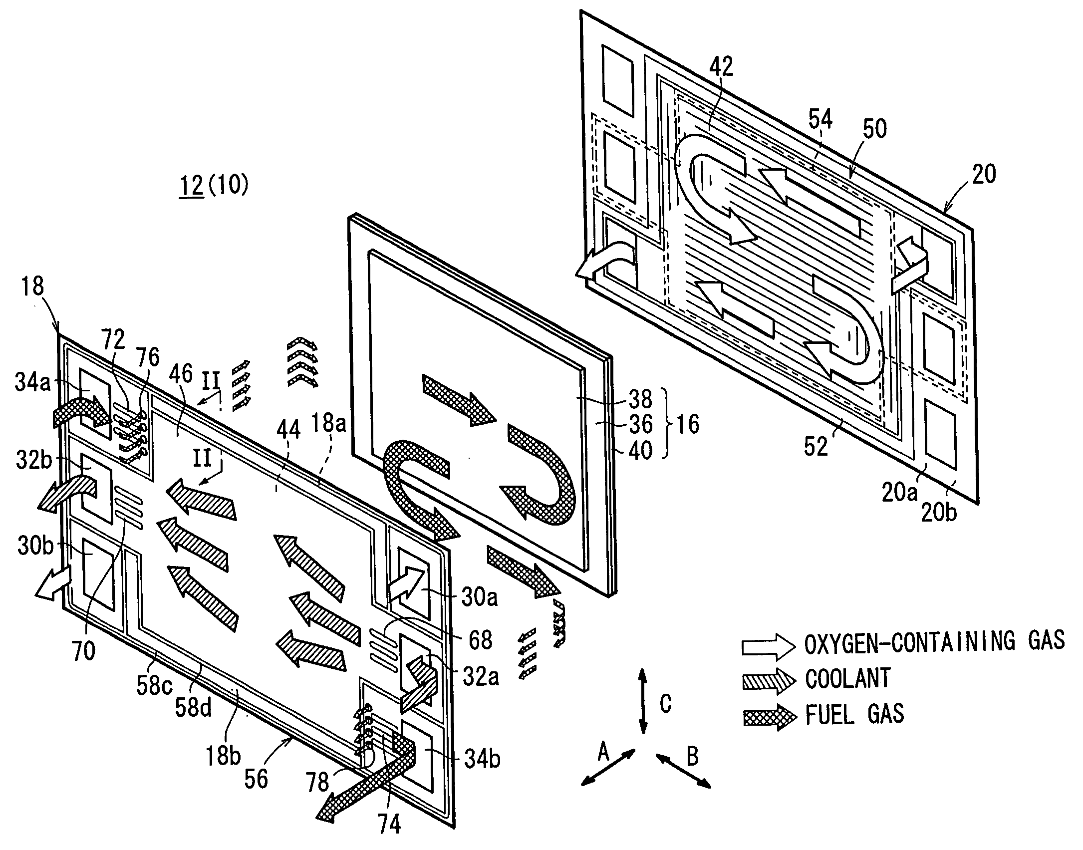
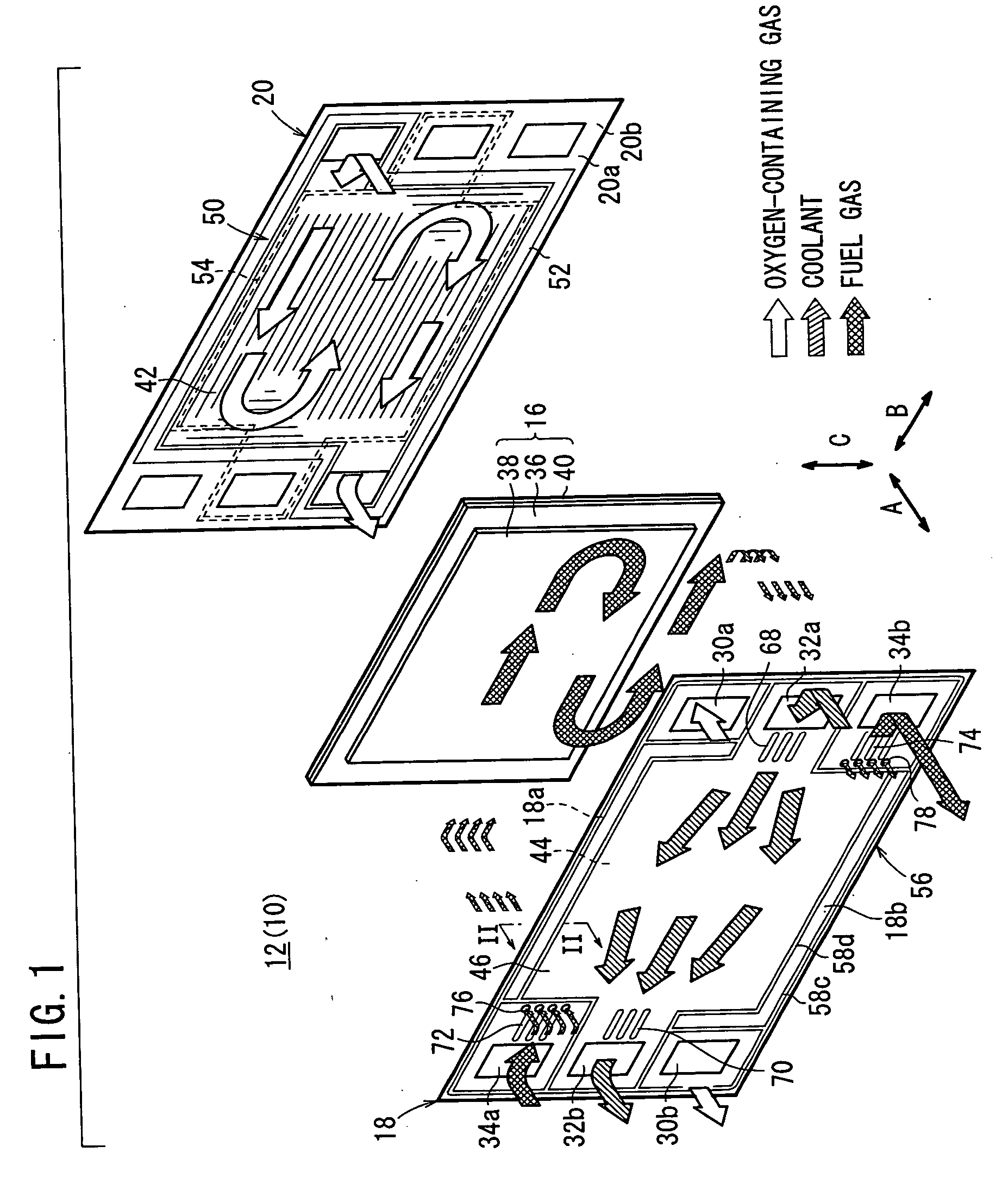
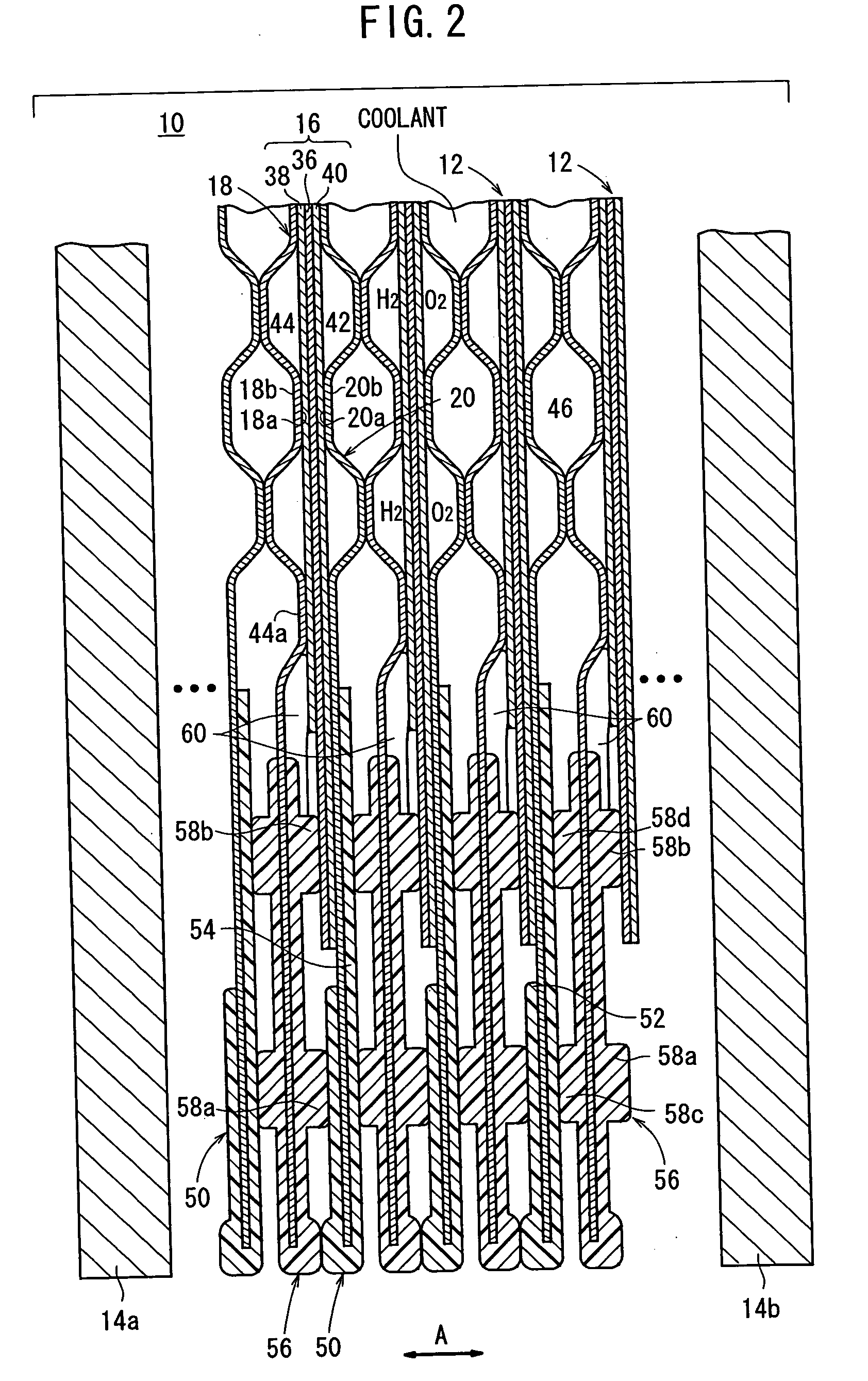
[0053]FIG. 1 is an exploded perspective view showing main components of a power generation cell 12 of a fuel cell 10 according to the present invention. FIG. 2 is a cross sectional view taken along a line II-II in FIG. 1, showing the fuel cell 10 formed by stacking a plurality of the power generation cells 12 in a stacking direction indicated by an arrow A.
[0054] As shown in FIG. 2, the fuel cell 10 is formed by stacking the power generation cells 12 in the direction indicated by the arrow A. At opposite ends of the fuel cell 10 in the stacking direction, end plates 14a, 14b are provided. The end plates 14a, 14b are fixed to the fuel cell 10 by tie rods (not shown) for tightening the power generation cells 12 with a predetermined tightening force in the direction indicated by the arrow A.
[0055] As shown in FIG. 1, the power generation cell 12 includes a membrane electrode assembly 16 and an anode side first metal separator (first separator) 18 and a cathode side second metal separa...
third embodiment
[0097]FIG. 8 is a cross sectional view showing a fuel cell 100 according to the present invention. Each of power generation cells 102 of the fuel cell 100 has a first metal separator 104. A second seal member 106 is formed integrally on both surfaces 104a, 104b of the first metal separator 104. The second seal member 106 includes an outer seal 58a and an inner seal 58b provided on the surface 104a of the first metal separator 104. A plurality of liquid seals (closure seals) 108 are provided at predetermined positions between the inner seal 58b and the protrusion 44a (see FIGS. 8 and 9).
[0098] The process of providing the liquid seals 108 will be described. Firstly, as shown in FIG. 10, when the first metal separator 104 and the second metal separator 20 are spaced away from each other, the liquid seal 108 is applied to the space between the inner seal 58b and the protrusion 44a. Then, as shown in FIG. 11, the first metal separator 104 and the second metal separator 20 move toward ea...
fourth embodiment
[0101]FIG. 12 is an exploded perspective view showing main components of a power generation cell 122 of a fuel cell 120 according to the present invention.
[0102] The power generation cell 122 includes a membrane electrode assembly 124, a first metal separator 126, and a second metal separator 128. The membrane electrode assembly 124 includes an anode 38a, a cathode 40a, and a solid polymer electrolyte membrane 36a interposed between the anode 38a and the cathode 40a. The solid polymer electrolyte membrane 36a has a passage such as an oxygen-containing gas supply passage 30a. The surface area of the anode 38a is substantially the same as the surface area of the cathode 40a (see FIG. 13).
[0103] A first seal member 130 is formed integrally on surfaces 128a, 128b of the second metal separator 128 to cover (sandwich) the outer edge of the second metal separator 128. The first seal member 130 includes a frame like seal surface 132 provided on the surface 128a of the second metal separato...
PUM
| Property | Measurement | Unit |
|---|---|---|
| thickness | aaaaa | aaaaa |
| angle | aaaaa | aaaaa |
| surface area | aaaaa | aaaaa |
Abstract
Description
Claims
Application Information