Inorganic optical taggant and method of making

a technology of optical taggant and inorganic chemistry, applied in inorganic chemistry, machines/engines, nuclear engineering, etc., can solve the problems of unstable or unpredictable, catastrophic detonation, and difficult and cheap dispersion of taggant material

Inactive Publication Date: 2005-05-31
UT BATTELLE LLC
View PDF13 Cites 45 Cited by
  • Summary
  • Abstract
  • Description
  • Claims
  • Application Information

AI Technical Summary

Benefits of technology

[0010]The present invention is intended to overcome many of the shortcomings of earlier approaches and simultaneously satisfy more of the desired performance attributes for a robust, flexible taggant system.
[0011]Accordingly, it is one object of the present invention to provide a taggant material that is inert and easily blended with explosive materials without degrading stability or explosive performance.
[0012]It is another object of the present invention to provide a taggant material that is easily detected after an explosion and displays a unique, traceable combination of physical characteristics.
[0014]It is still yet another object of the present invention to provide a taggant material that is environmentally stable so that it may be recovered after some exposure to the elements without losing its distinctive properties.
[0016]It is another object of the present invention to provide a method of making an inorganic taggant material in numerous compositional and size variants so that a large number of uniquely identifiable batches may be created.

Problems solved by technology

First, the taggant material must be easily and cheaply dispersed throughout a batch of explosive material using traditional formulating and blending equipment.
At the same time, explosives, by their very nature, must be formulated carefully and the industry is understandably reluctant to add materials that might make them unstable or unpredictable.
In particular, taggants made from small bits of plastic might be a source of static electricity that could lead to catastrophic detonation during processing, mixing, or loading cartridges.
Users will also balk if the performance of the explosive is degraded or if significant costs are added.
Both the ferrite and the magnetite materials are, however, dark colored and absorptive of the radiation which excites the luminescent material, thereby making the particles somewhat difficult to locate after an explosion.

Method used


Image

  • Inorganic optical taggant and method of making
  • Inorganic optical taggant and method of making

Examples


example 1

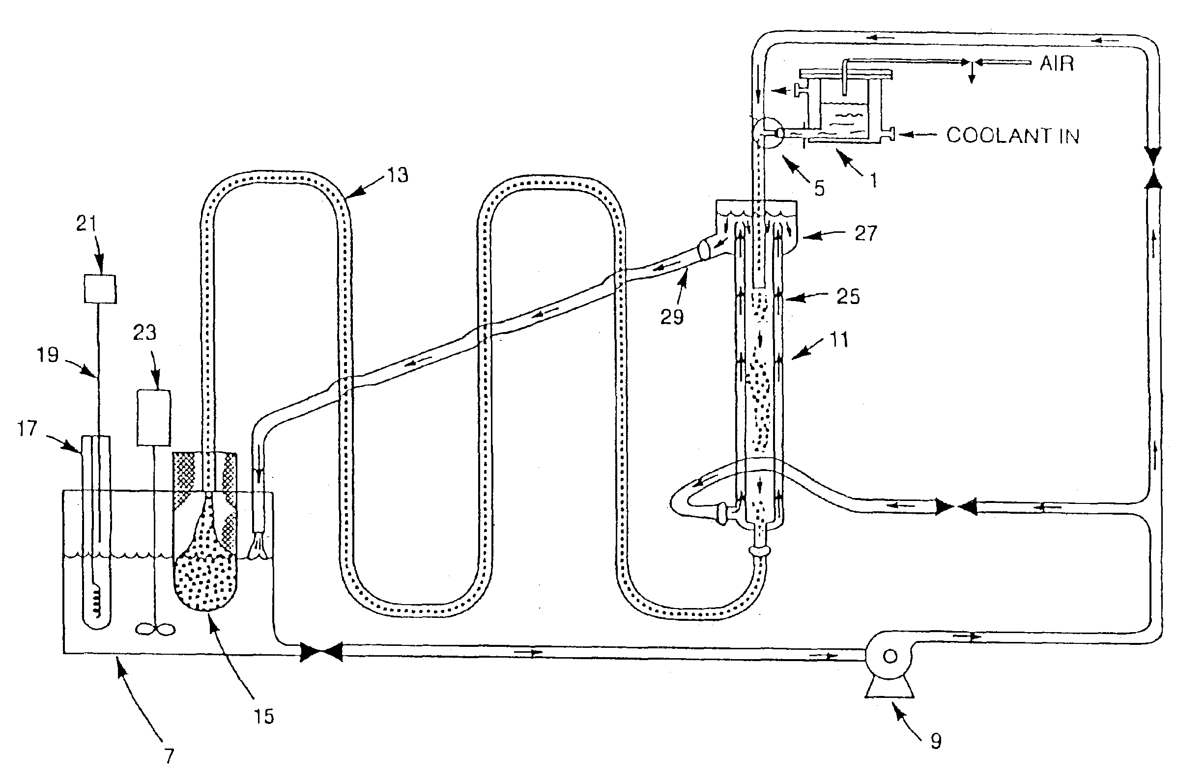
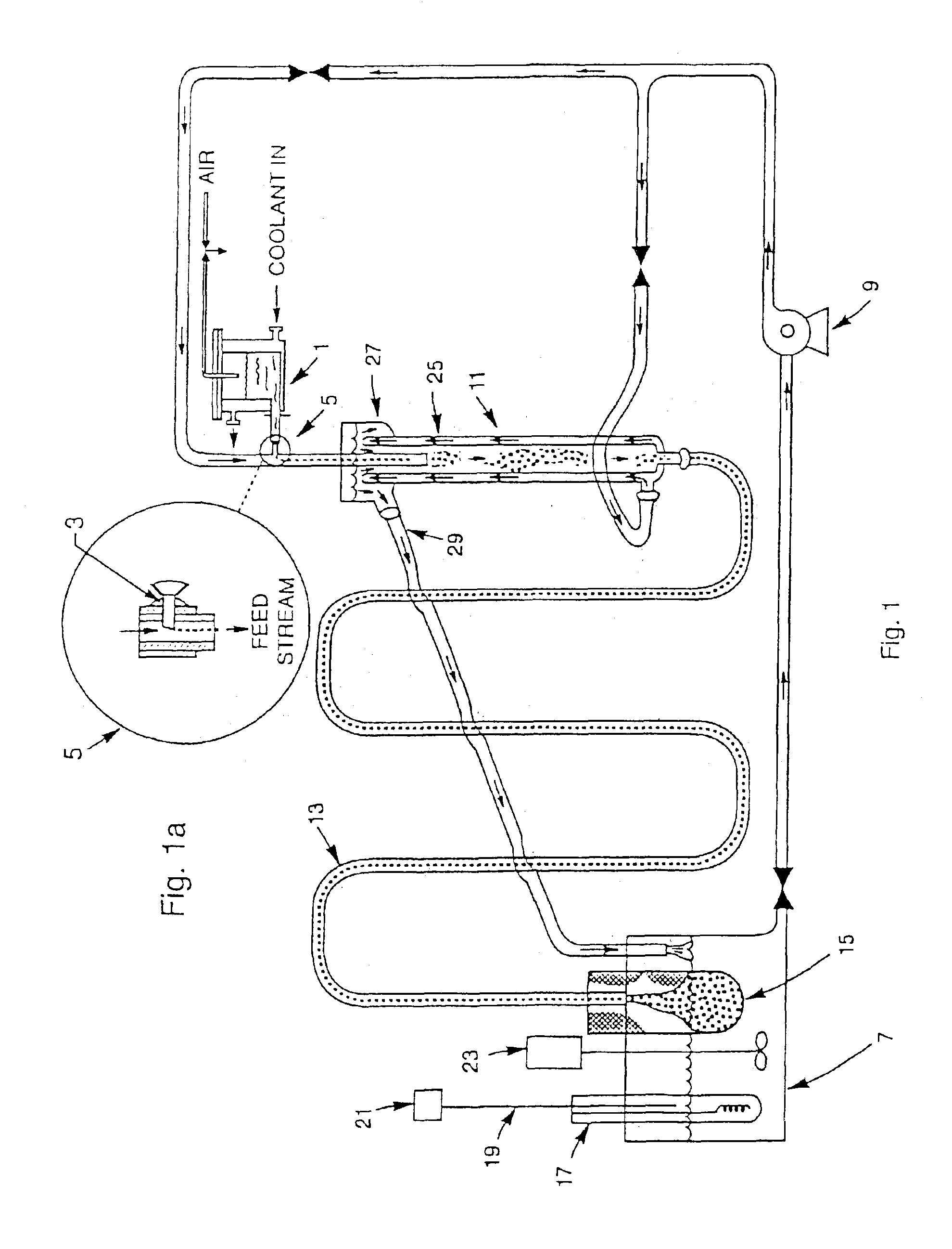
[0049]Hydrous zirconium oxide (HZrO) gel beads were made by internal gelation using the technique and apparatus, described above and as shown in FIG. 1 and FIG. 1a, also described by Collins. A feed broth containing 100 ml zirconyl nitrate, 14.5 ml nitric acid, and 70 ml hexamethylenetetramine (HMTA) was injected into warm silicone oil, as described in U.S. Pat. No. 5,821,186, to form spherical gel beads. The beads were dried in air to form small glassy beads, which were then soaked in a solution of 1% Eu nitrate, dried again, and fired in air at 1° C. / min to 1000° C. The fired beads were opaque off-white color. Under UV illumination, the beads displayed a weak red fluorescence.

[0050]Skilled artisans will appreciate that hydrous oxides of other Group IV metals, e.g., Ti may be made by a similar approach (see, for example, Collins, U.S. Pat. No. 5,821,186, the teachings of which are incorporated herein by reference). Furthermore, it is well known that rare earth phosphates are anothe...

example 2

[0051]Wet hydrous zirconium oxide (HZrO) gel beads, made by the method described above, were washed several times in 0.5 M phosphoric acid, allowed to stand about four hours in this solution, then washed several times in 1.0 M phosphoric acid. Hydrothermal conversion was done at 125° C. in 1.0 M phosphoric acid in a closed stainless steel vessel. The conversion step was then repeated several more times, each time increasing the phosphoric acid concentration by 0.5 M until the final treatment was done in 2.5 M phosphoric acid. This material had been dried to form glassy beads. When these dried beads were placed in a 1% Eu nitrate solution, they fractured into concentric shards during rehydration, but absorbed the solution adequately. These fragments were dried and fired in air as in the previous example. Under UV illumination, the particles were very strongly fluorescent (bright red).

example 3

[0052]An attempt was made to avoid the cracking problem encountered when dried HZrP beads were rehydrated. Using the materials and procedures of the previous example, hydrous zirconia beads were reacted with phosphoric acid and washed. While still wet, the HZrP gel beads were placed overnight in a 1% Eu nitrate solution, then dried for several days and fired in air at 1° C. / min to 1000° C. A similar batch was placed overnight in a 1% Ce nitrate solution, dried, and fired in air at 1° C. 1 min to 1000° C.


PUM

PropertyMeasurementUnit
diameteraaaaaaaaaa
diameteraaaaaaaaaa
temperaturesaaaaaaaaaa

Abstract

Sintered, translucent ceramic microbeads, preferably alumina, titania, zirconia, yttria, zirconium phosphate, or yttrium aluminum garnet (YAG) are doped with one or more optically active species. The beads may be added to substances such as explosives in order to create a distinctive optical signature that identifies a manufacturer, lot number, etc. in the event of the need for forensic analysis. Because the beads have a generally spherical surface, the radius of curvature provides an additional distinguishing characteristic by which a particular sample may be identified. The beads could also be formulated into paints if needed to create distinctive optical signatures for camouflage, decoys, or other countermeasures and could also be applied as a dust to track the movement of personnel, vehicles, etc.

Description

[0001]This invention was made with Government support under Contract No. DE-AC05-00OR22725 awarded by the U.S. Department of Energy to UT-Battelle, LLC, and the Government has certain rights in this invention.FIELD OF THE INVENTION[0002]This invention relates to the field of optical taggants and more specifically, to materials and methods for tagging explosives and propellants for forensic identification, quality control, and other purposes.BACKGROUND OF THE INVENTION[0003]There is an ongoing desire within the law enforcement communities to have a way of recognizing or tracing explosives that have been used in a crime. It will be appreciated that a useful taggant will need to satisfy a number of challenging performance requirements. First, the taggant material must be easily and cheaply dispersed throughout a batch of explosive material using traditional formulating and blending equipment. At the same time, explosives, by their very nature, must be formulated carefully and the indus...

Claims


Application Information

Patent Timeline
Patent Type & Authority Patents(United States)
IPC IPC(8): C09K11/00H01M4/00H01M6/04H01M6/10C09K11/77
CPCC09K11/7729C01B25/372C01G23/04C01G25/02C04B35/44C04B35/486C04B35/624C04B2235/9653Y10S252/965C01P2002/54C01P2004/61C01P2006/60C04B2235/3224C04B2235/3229C04B2235/764C04B2235/94Y10S149/123
Inventor LAUF, ROBERT J.ANDERSON, KIMBERLY K.MONTGOMERY, FREDERICK C.
Owner UT BATTELLE LLC
Why Eureka
Try Eureka