Fuel cell system having an integral turbine/compressor unit

a fuel cell and compressor unit technology, applied in the field of fuel cell systems, can solve the problems of requiring a comparatively large amount of installation space, complex structure form, and complex construction of this german patent document, and achieve the effects of reducing water condensation, simple and efficient cooling, and not adversely affecting the performance of the fuel cell

Inactive Publication Date: 2015-06-30
DAIMLER AG
View PDF21 Cites 1 Cited by
  • Summary
  • Abstract
  • Description
  • Claims
  • Application Information

AI Technical Summary

Benefits of technology

[0005]German Utility Model DE 20 2005 017 574 U1 discloses a split cage motor for driving a recirculation conveying means for recirculating anode exhaust gas around the anode chamber of a fuel cell. The advantage of such a split cage motor is that the hydrogen carrying region together with the rotor can be sealed off hermetically with respect to the stator of the split cage motor, so that there are no complications with regard to the sealing off of hydrogen carrying regions.
[0020]In a particularly beneficial method for driving a recirculation conveying means in a fuel cell system the electric drive motor can be designed for a constant or approximately constant operating point. This designing of the electric drive motor for a constant or approximately constant operating point and the variation of the drive power required for the compressor wheel by a corresponding variation of the hydrogen flow onto the turbine makes it possible to use a very simple and inexpensive electric drive motor with correspondingly simple and inexpensive electronics, since said motor, due to the constant or approximately constant operating point for which it is designed, can be realized correspondingly simply and efficiently and only a low mechanical drive power has to be provided. A large spread of speeds can be dispensed with, so that as a result of this, in addition to an improvement in the efficiency, a reduction in costs, installation space and weight can also be achieved. The electric drive motor as a result can preferably be designed as a low voltage motor.

Problems solved by technology

The construction in this German patent document is comparatively complex, and is costly with regard to the sealing and the mixing of the recirculated gas flow and the fresh hydrogen.
The complex structural form furthermore requires a comparatively large amount of installation space, and is correspondingly heavy.
Using a Laval nozzle in such case, however, is disadvantageous because the desired effect can be achieved merely at a single load point or in the region of a single load point of the fuel cell system.
In addition to the structural volume, this also saves on weight and costs.
Furthermore, in certain operating states the energy in the region of the turbine alone is not sufficient to drive the recirculation conveying means due to the admetered amount of fresh hydrogen being very small.
The latter can therefore cool the components without additional cooling media having to be brought into the hydrogen carrying region, with corresponding expense with regard to sealing.

Method used


Image

  • Fuel cell system having an integral turbine/compressor unit
  • Fuel cell system having an integral turbine/compressor unit
  • Fuel cell system having an integral turbine/compressor unit

Examples


Embodiment Construction

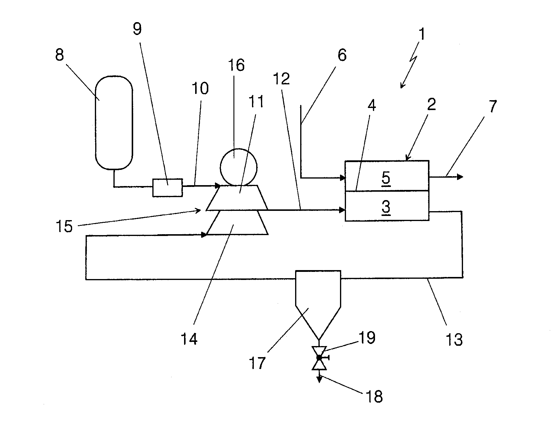
[0026]In the illustration of FIG. 1, a section of a fuel cell system 1 can be recognized in very highly diagrammatic form. The system has a fuel cell 2 in the form of a PEM fuel cell. In such a PEM fuel cell, which is typically stacked as a stack consisting of a large number of individual cells, anode chambers 3 are separated from cathode chambers 5 by means of a proton conducting membrane 4. The cathode chambers or the cathode chamber 5 in this case is / are supplied with air as oxygen supplier via an incoming air line 6; unspent exhaust air passes out of the fuel cell system 1 via an exhaust air line 7. Since the region of the air supply of the cathode chamber 5 is of no further relevance for the invention presented here, it will not be discussed in greater detail. It may, however, be formed in any manner whatsoever which is known per se with corresponding conveying means, air filters, recirculation of the exhaust air, utilization of pressure energy and thermal energy in the exhaust...


PUM

PropertyMeasurementUnit
pressuresaaaaaaaaaa
voltageaaaaaaaaaa
pressureaaaaaaaaaa

Abstract

A fuel cell system includes at least one fuel cell having an anode chamber, a cathode chamber, a hydrogen pressure reservoir, a recirculation line connecting an outlet of the anode chamber to an inlet of the anode chamber, a recirculation conveyor with a compressor wheel in the region of the recirculation line, and a turbine for expanding the hydrogen that is under pressure before entry into the anode chamber. The recirculation conveyor is driven at least partially by the turbine. The turbine and the compressor wheel are formed in one component.

Description

BACKGROUND AND SUMMARY OF THE INVENTION[0001]Exemplary embodiments of the present invention relate to a fuel cell system.[0002]German patent document DE 10 2006 003 799 B4 describes a fuel cell system in which pressure is relieved from a hydrogen pressure reservoir in a turbine. This turbine then, at least partially, drives a recirculation conveying means in the region of a recirculation line around an anode chamber of at least one fuel cell of the fuel cell system. The construction, which may also have for assistance an electric motor drive for recirculation conveying means, in such case utilizes the pressure energy in the hydrogen pressure reservoir upon the expansion of the hydrogen that is necessary anyway, in order to utilize said energy for driving the recirculation conveying means.[0003]The construction in this German patent document is comparatively complex, and is costly with regard to the sealing and the mixing of the recirculated gas flow and the fresh hydrogen. The compl...

Claims


Application Information

Patent Timeline
Patent Type & Authority Patents(United States)
IPC IPC(8): H01M8/04F01D1/02H01M8/10
CPCH01M8/04097F01D1/026H01M8/04111H01M8/04164H01M8/04014H01M8/04201H01M2008/1095Y02E60/50
Inventor HAUSMANN, PHILIPPKNOOP, ANDREAS
Owner DAIMLER AG
Why Eureka
Try Eureka