Driving circuit and error amplifier thereof

a driving circuit and error amplifier technology, applied in the field of electronic circuits, can solve the problems of high error current required to quickly charge the compensation capacitor, oscillation of the driving circuit, etc., and achieve the effect of high start-up speed

Active Publication Date: 2015-06-30
HIMAX ANALOGIC INC
View PDF5 Cites 0 Cited by
  • Summary
  • Abstract
  • Description
  • Claims
  • Application Information

AI Technical Summary

Benefits of technology

[0010]Thus, through application of one of the embodiments mentioned above, the error amplifier with an adjustable error current can be implemented. By charging the compensation capacitor operatively with both the main and the auxiliary output stage of the error amplifier or with merely the main output stage of the error amplifier, a stable driving circuit with a high start-up speed can be implemented.

Problems solved by technology

Generally, a high error current is required to charge the compensation capacitor quickly during a start-up period.
However, such high error current may induce the oscillation of the driving circuit while the driving circuit is activated and in operation.
Therefore, the compensation capacitor with a high capacitance, which undesirablly blocks the charge speed of the compensation capacitor, is still needed to keep the driving circuit from the oscillation.

Method used


Image

  • Driving circuit and error amplifier thereof
  • Driving circuit and error amplifier thereof
  • Driving circuit and error amplifier thereof

Examples


Embodiment Construction

[0015]In the following detailed description, for purposes of explanation, numerous specific details are set forth in order to attain a thorough understanding of the disclosed embodiments. It will be apparent, however, that one or more embodiments may be practiced without these specific details. In other instances, well-known structures and devices are schematically shown in order to simplify the drawing.

[0016]For the term “electrically connect” or “connect” used herein, both of them can refer to the physical contact or electrical contact performed directly or indirectly between two or more elements. The term “electrically connect” or “connect” can further refer to the interoperation or interaction between two or more elements.

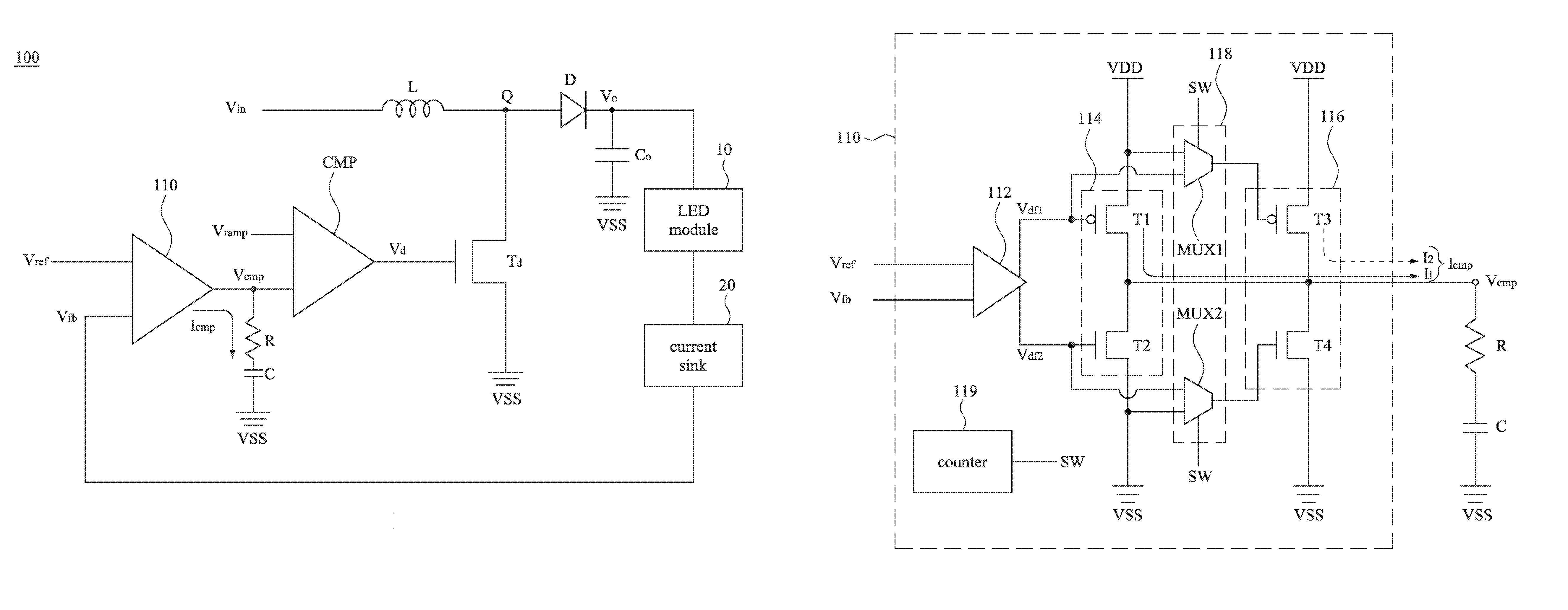
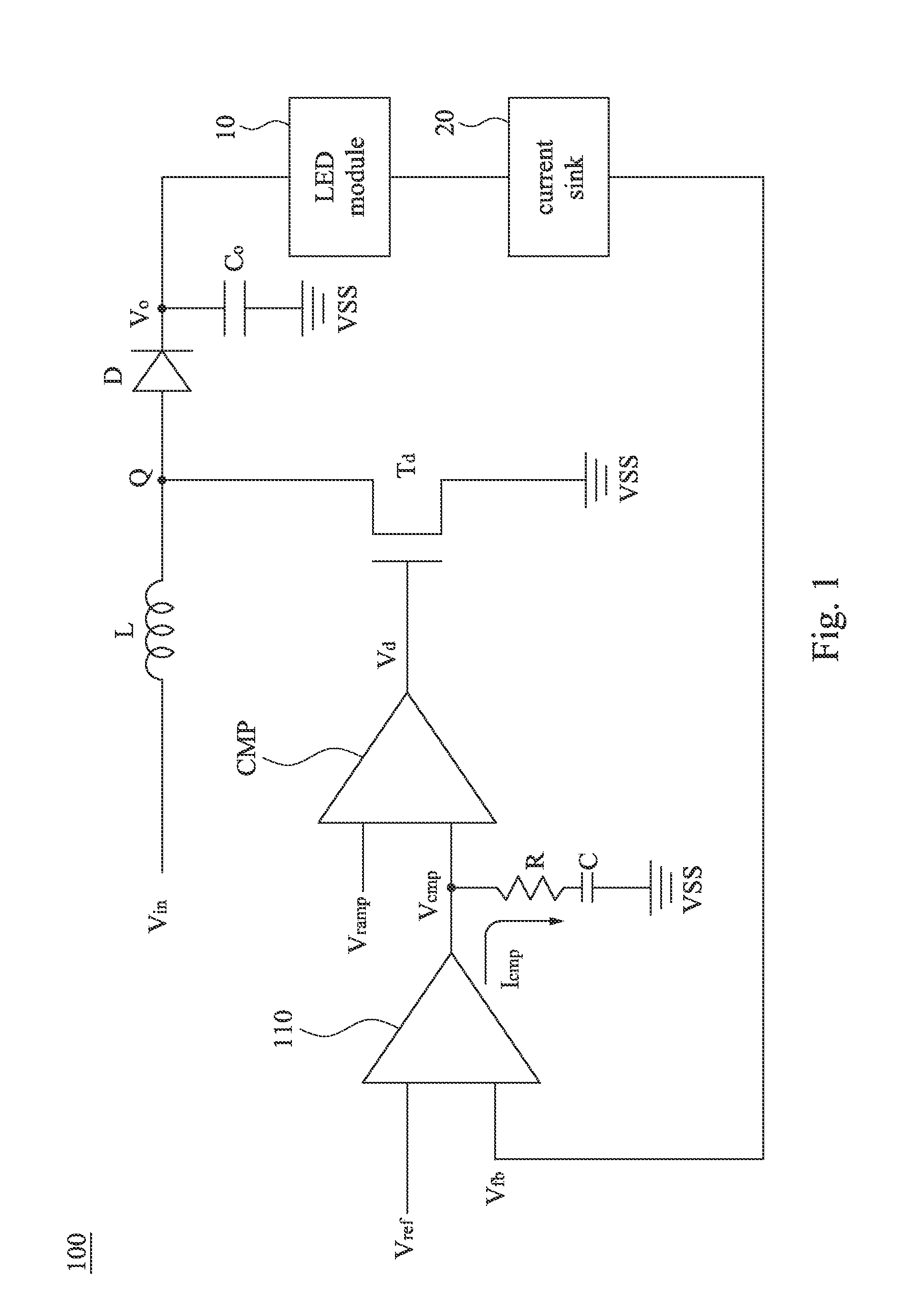
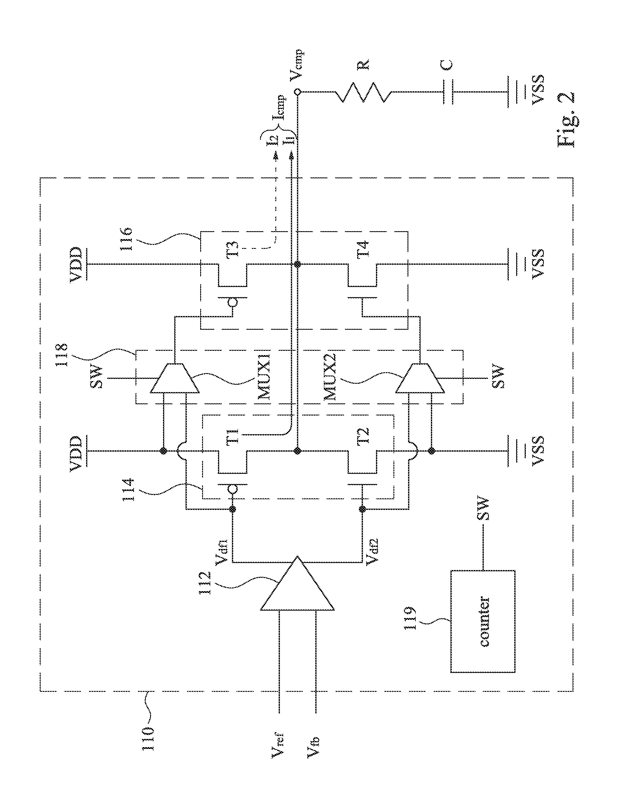
[0017]One aspect of the invention provides a driving circuit. For the purpose of clear description, a LED driving circuit will be taken as an example in the following paragraphs. However, the invention is not limited to the embodiment following described.

[0018]...


PUM


Abstract

An error amplifier and a driving circuit are disclosed herein. The error amplifier is configured to charge a compensation capacitor with an error current. The error amplifier includes an input stage, a main output stage, and an auxiliary output stage. The input stage is configured to provide a first differential output signal and a second differential output signal in response to a comparison between a reference voltage and a feedback voltage. The main output stage is configured to charge the compensation capacitor. The auxiliary output stage is configured to be activated to charge the compensation capacitor. a first operation, both the main output stage and the auxiliary output stage charge the compensation capacitor. In a second operation, the main output stage charges the compensation capacitor, and the auxiliary output stage is deactivated and does not charge the compensation capacitor.

Description

BACKGROUND[0001]1. Technical Field[0002]The present disclosure relates to an electronic circuit. More particularly, the present invention relates to a driving circuit and an error amplifier thereof.[0003]2. Description of Related Art[0004]Light emitting diodes (LEDs) are in estimation four times as efficient as conventional incandescent lights. The LEDs are also considered to be more economically sound than compact fluorescent bulbs that contain environmentally harmful mercury required further processing, and are supposed to last longer than that the conventional lighting does. In this regard, the LEDs have been becoming the mainstream of the lighting technology.[0005]A driving circuit for driving the LEDs includes an error amplifier for comparing a reference voltage with a feedback voltage to charge a compensation capacitor with an error current. The charge speed of the compensation capacitor corresponds to both the capacitance of the compensation capacitor and the magnitude of the...

Claims


Application Information

Patent Timeline
Patent Type & Authority Patents(United States)
IPC IPC(8): H02M3/156
CPCH02M3/156H05B45/14H05B45/38
Inventor TSENG, KUAN-JEN
Owner HIMAX ANALOGIC INC
Why Eureka
Try Eureka