Cracked cap bulkhead insert

a bulkhead insert and insert technology, applied in the field of internal combustion engines, can solve the problems of limiting the force the upper coupling parts can support, increasing the volume and mass of the insert, and limiting the mitigation of cylinder bore distortion, so as to increase the stiffness and structural integrity of the block

Active Publication Date: 2015-07-21
FORD GLOBAL TECH LLC
View PDF18 Cites 6 Cited by
  • Summary
  • Abstract
  • Description
  • Claims
  • Application Information

AI Technical Summary

Benefits of technology

[0002]Cylinder or engine blocks form part of an internal combustion engine and may include cylinder bores at least partially forming spaces into which pistons may be inserted. A cylinder head may be disposed above the cylinder block to form the cylinders, while a crankcase may be disposed below the cylinder block to support a crankshaft. The cylinder block may include a plurality of bulkhead inserts to provide support to the crankshaft via bearings, couple the cylinder head to the overall cylinder block, and increase the stiffness and structural integrity of the block.
[0004]The inventors herein have recognized several issues with such an approach. First, the upper coupling parts may be limited in the amount of force they can support, due to their outwardly extending spoke-like configuration. Such extension further increases the volume and mass of the inserts. Moreover, spacing between adjacent cylinder bores in the engine block may be increased due to the volume occupied by the upper coupling parts. Finally, the spoke-like configuration may limit mitigation of cylinder bore distortion during engine operation.
[0005]Bulkhead inserts having a cracked cap and an improved structure for strength and stiffness are provided.
[0007]In this way, the overall weight of a cylinder block may be reduced, in turn improving fuel economy. The plurality of inserts may further facilitate a reduction in noise, vibration, and harshness, required machining, crankshaft weight, and a number of fastening devices needed to secure the inserts in the cylinder block.

Problems solved by technology

First, the upper coupling parts may be limited in the amount of force they can support, due to their outwardly extending spoke-like configuration.
Such extension further increases the volume and mass of the inserts.
Finally, the spoke-like configuration may limit mitigation of cylinder bore distortion during engine operation.

Method used


Image

  • Cracked cap bulkhead insert
  • Cracked cap bulkhead insert
  • Cracked cap bulkhead insert

Examples


Embodiment Construction

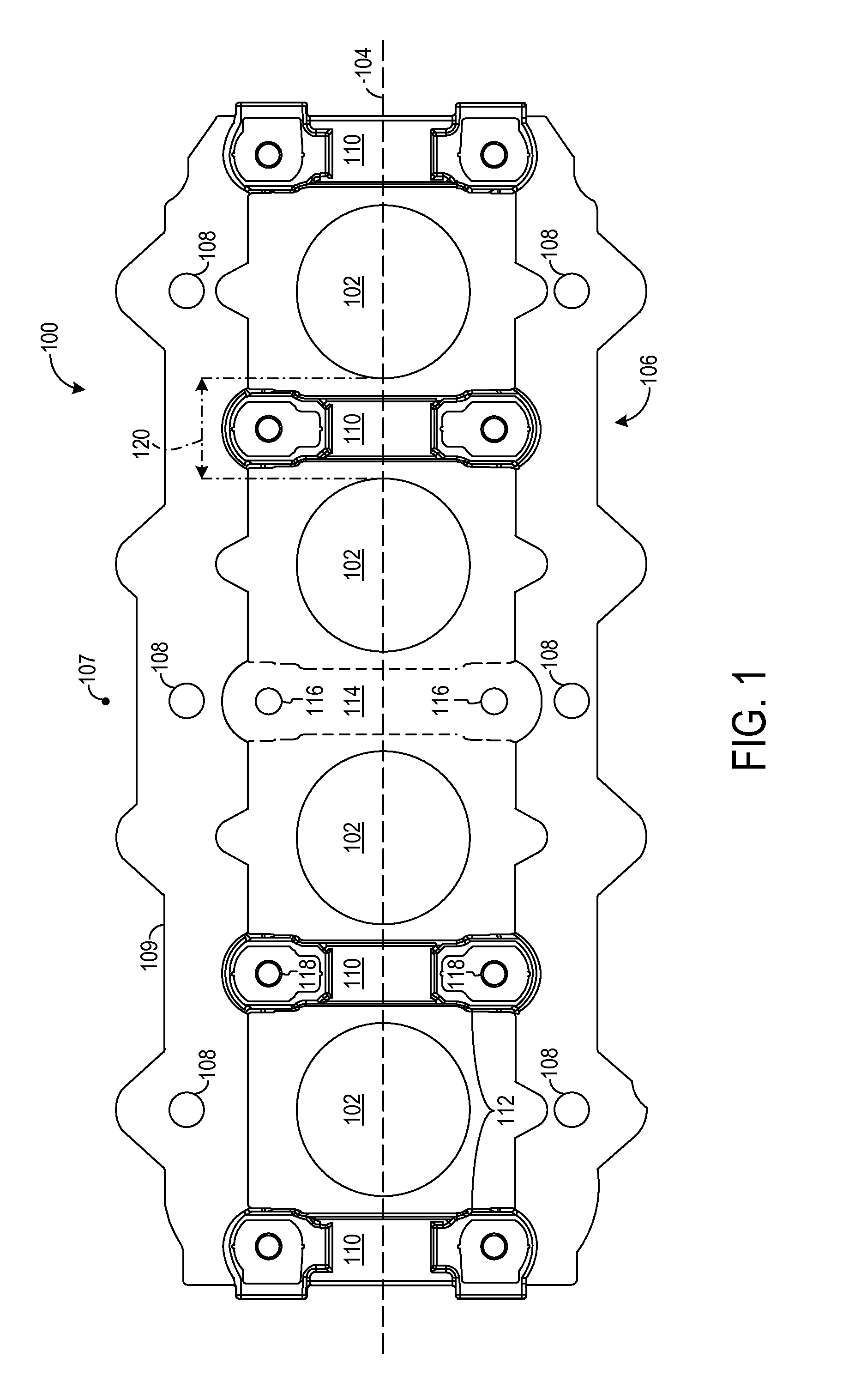
[0015]Cylinder blocks may include a plurality of bulkhead inserts to reinforce the block and improve load distribution throughout the block. Some bulkhead inserts may be vertically oriented, perpendicular to a crankshaft axis, and include a bore to support insertion and rotation of a crankshaft. Conventional bulkhead inserts comprised of cast iron, however, cannot be cracked or otherwise segmented into two or more pieces, increasing the difficulty of crankshaft insertion and cylinder block assembly, and requiring additional machining.

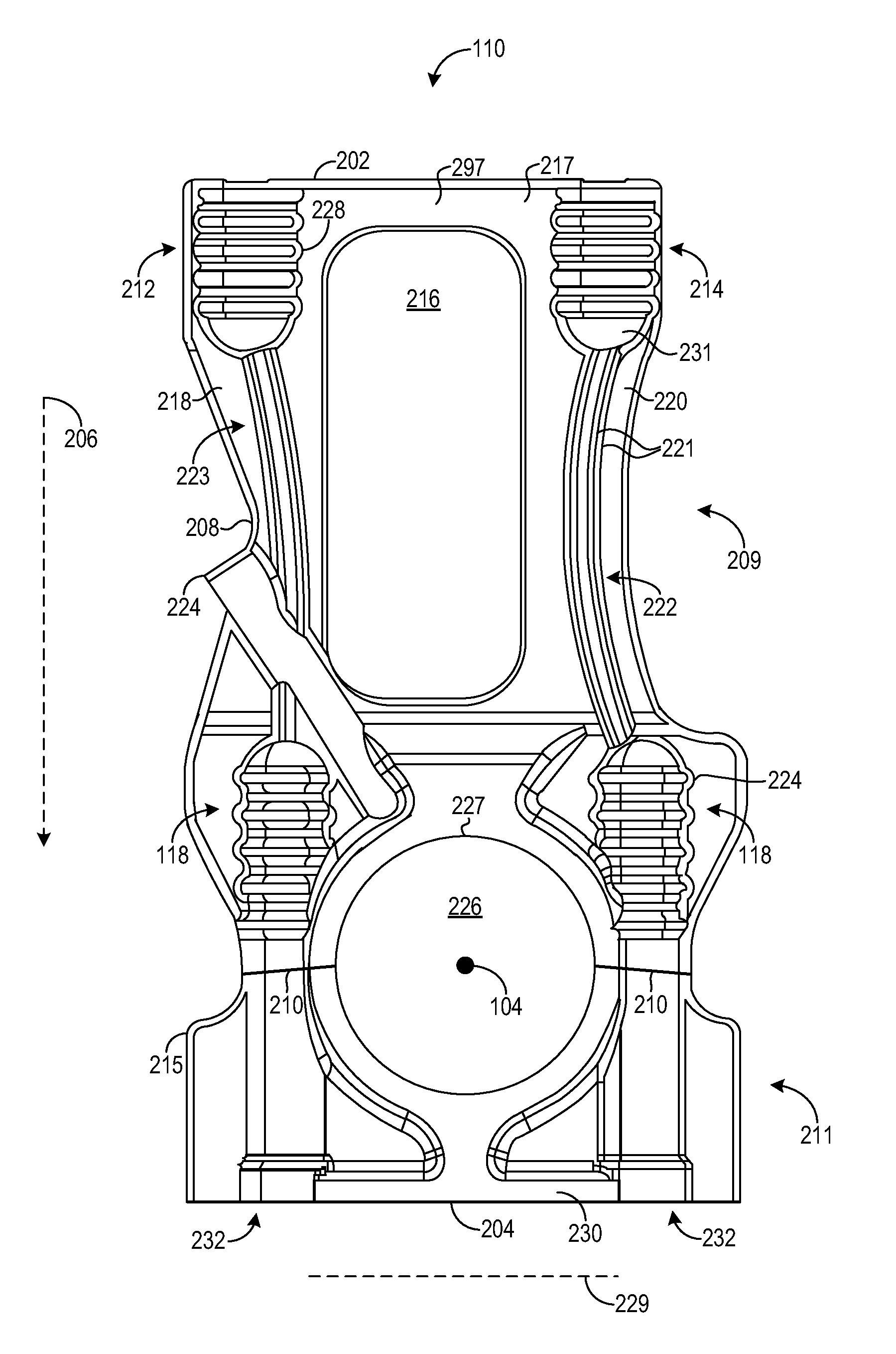
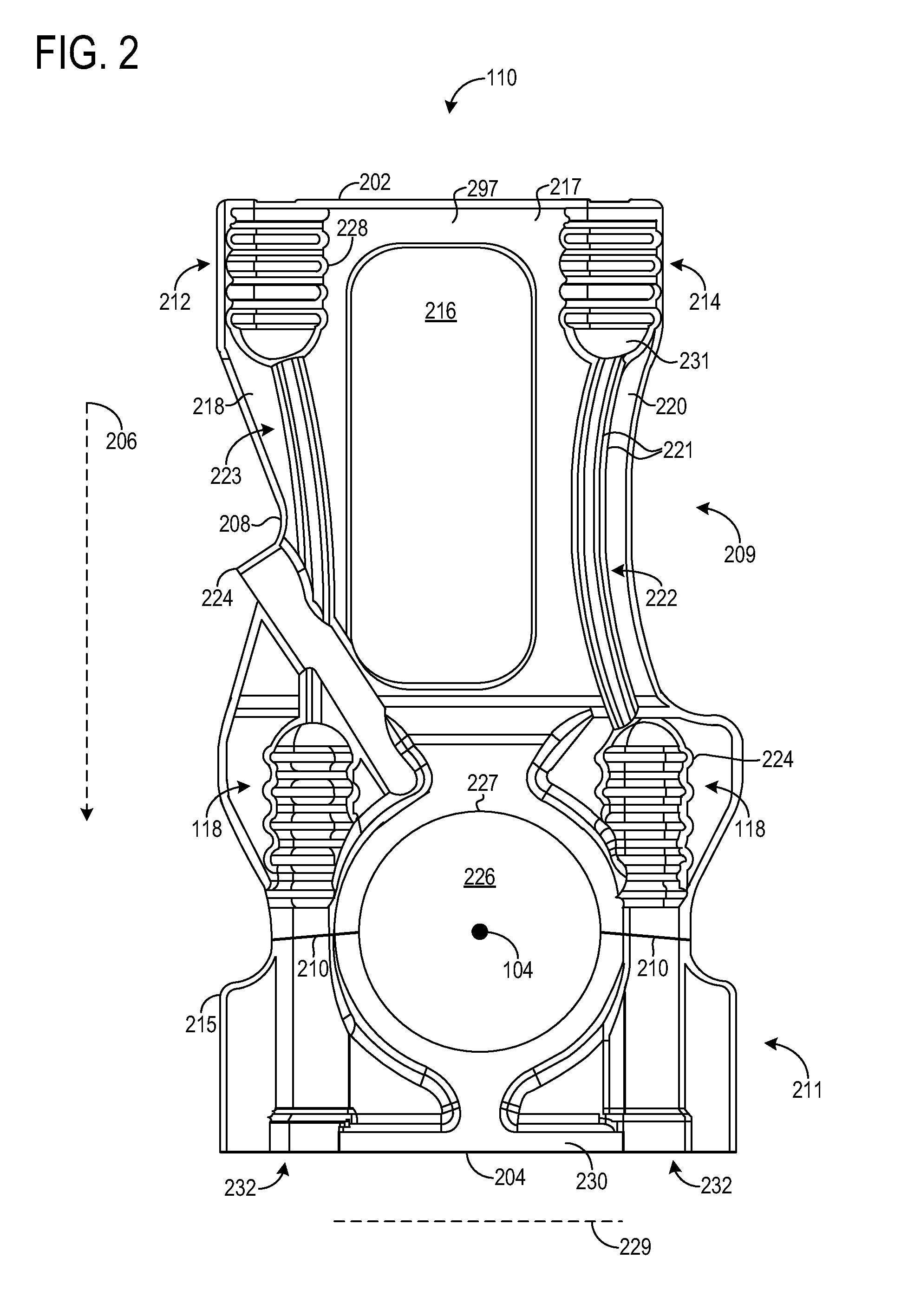
[0016]Bulkhead inserts having a cracked cap and an optimized structure for strength and stiffness are provided. In some embodiments, the inserts may include an upper portion and a cap disposed below the upper portion, the cap cracked from the upper portion and rejoined to the upper portion by one or more fastening devices. The upper portion may have one or more upper bosses, with each upper boss have a surface with extruded, circumferentially-extending ...


PUM


Abstract

Various bulkhead inserts having a cracked cap are provided. In one example, a cylinder block includes a plurality of cylinder bores, a crankcase disposed below the cylinder block in a vertical direction, and a plurality of inserts, where each adjacent pair of inserts of the plurality of inserts partitions each cylinder bore of the plurality of cylinder bores. Each insert of the plurality of inserts has an upper portion and a cap disposed below the upper portion, the cap cracked from the upper portion and rejoined to the upper portion by one or more fastening devices, the upper having one or more upper bosses, each upper boss having a surface with extruded, circumferentially-extending serrations.

Description

FIELD[0001]The disclosure relates to internal combustion engines and particularly to bulkhead inserts in a cylinder block.BACKGROUND AND SUMMARY[0002]Cylinder or engine blocks form part of an internal combustion engine and may include cylinder bores at least partially forming spaces into which pistons may be inserted. A cylinder head may be disposed above the cylinder block to form the cylinders, while a crankcase may be disposed below the cylinder block to support a crankshaft. The cylinder block may include a plurality of bulkhead inserts to provide support to the crankshaft via bearings, couple the cylinder head to the overall cylinder block, and increase the stiffness and structural integrity of the block.[0003]U.S. Pat. App. No. 2010 / 0050977 describes the inclusion of crankcase inserts in an engine block comprised of magnesium alloy. The crankcase inserts may be comprised of compacted graphite iron (CGI) and inserted below and between a plurality of cylinder chambers. Each inse...

Claims


Application Information

Patent Timeline
Patent Type & Authority Patents(United States)
IPC IPC(8): F02B67/00F02F7/00F02B75/02
CPCF02F7/0021F02B2075/025F02F7/0007F02F7/0012F02F7/0053F05C2201/021
Inventor WILLIAMS, RICK L.MAKI, CLIFFMULLINS, JEFFREY ALLEN
Owner FORD GLOBAL TECH LLC
Why Eureka
Try Eureka