

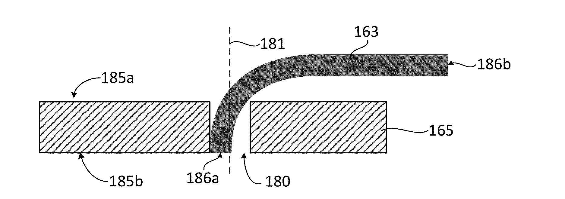
Method for forming an optical fiber array
a technology of optical fiber arrays and optical fibers, applied in nanoinformatics, applications, instruments, etc., can solve problems such as difficult placement and accurate placement, and achieve the effect of increasing the stiffness and structural integrity of bent fibers
- Summary
- Abstract
- Description
- Claims
- Application Information
AI Technical Summary
Benefits of technology
Problems solved by technology
Method used
Image

Examples
Embodiment Construction
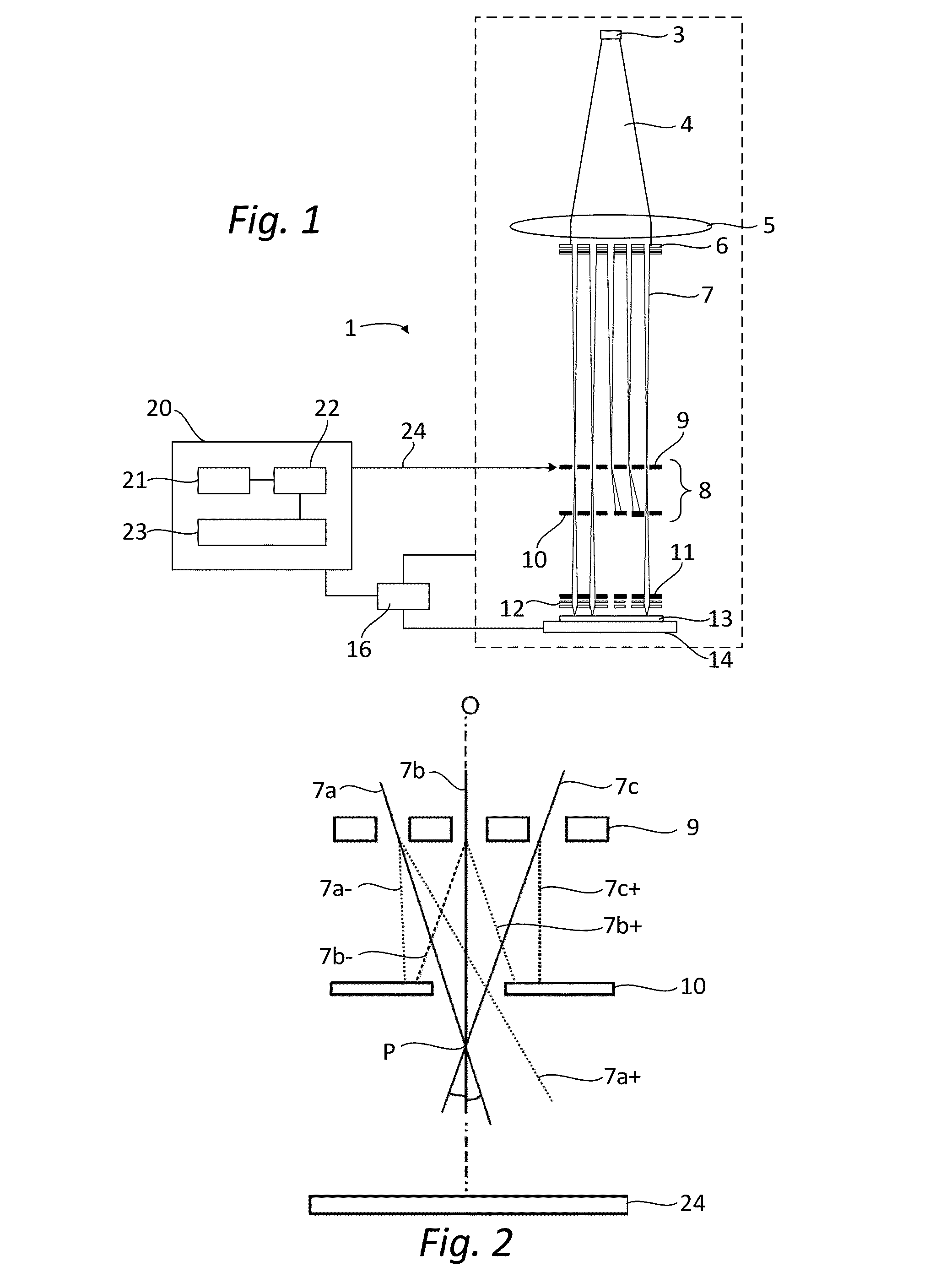
[0045]The following is a description of various embodiments of the invention, given by way of example only and with reference to the figures. The figures are not drawn to scale and merely intended for illustrative purposes.
[0046]FIG. 1 shows a simplified schematic drawing of an embodiment of a charged particle multi-beamlet lithography system 1. The lithography system 1 suitably comprises a beamlet generator generating a plurality of beamlets, a beamlet modulator patterning the beamlets to form modulated beamlets, and a beamlet projector for projecting the modulated beamlets onto a surface of a target.
[0047]The beamlet generator typically comprises a source and at least one beam splitter. The source in FIG. 1 is an electron source 3 arranged to produce a substantially homogeneous, expanding electron beam 4. The beam energy of the electron beam 4 is preferably maintained relatively low in the range of about 1 to 10 keV. To achieve this, the acceleration voltage is preferably low, and...
PUM
| Property | Measurement | Unit |
|---|---|---|
| beam energy | aaaaa | aaaaa |
| voltage | aaaaa | aaaaa |
| size | aaaaa | aaaaa |
Abstract
Description
Claims
Application Information