Arrangement of optical fibers, and a method of forming such arrangement

a technology of optical fibers and arrangement, applied in the field of arrangement of optical fibers, can solve problems such as difficult placement and precise placement, and achieve the effect of increasing the stiffness and structural integrity of bent fibers

Active Publication Date: 2015-05-19
ASML NETHERLANDS BV
View PDF30 Cites 3 Cited by
  • Summary
  • Abstract
  • Description
  • Claims
  • Application Information

AI Technical Summary

Benefits of technology

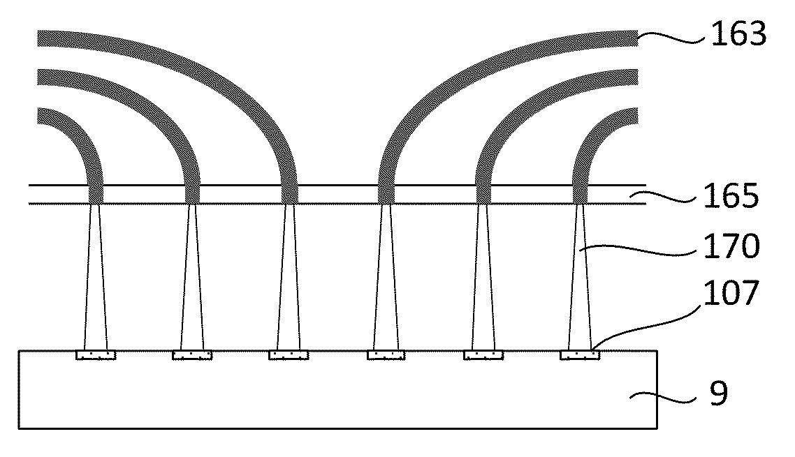
[0008]The fibers may have an outer jacket or coating which is stripped from the portion of the fibers inserted into the apertures, or the fibers may be inserted into the apertures without stripping. The fiber ends have a diameter smaller than the smallest diameter of the apertures, so that stripping the outer jacket or coating will reduce the required diameter of the apertures.
[0017]Bonding the bent fibers together may comprise: forming a mold around the plurality of bent fibers; filling the mold with an adhesive material; and curing the adhesive material. The resulting bonded structure increases the stiffness and structural integrity of the bent fibers.

Problems solved by technology

Such accurate placement is not straightforward.

Method used


Image

  • Arrangement of optical fibers, and a method of forming such arrangement
  • Arrangement of optical fibers, and a method of forming such arrangement
  • Arrangement of optical fibers, and a method of forming such arrangement

Examples


Embodiment Construction

[0044]The following is a description of various embodiments of the invention, given by way of example only and with reference to the figures. The figures are not drawn to scale and merely intended for illustrative purposes.

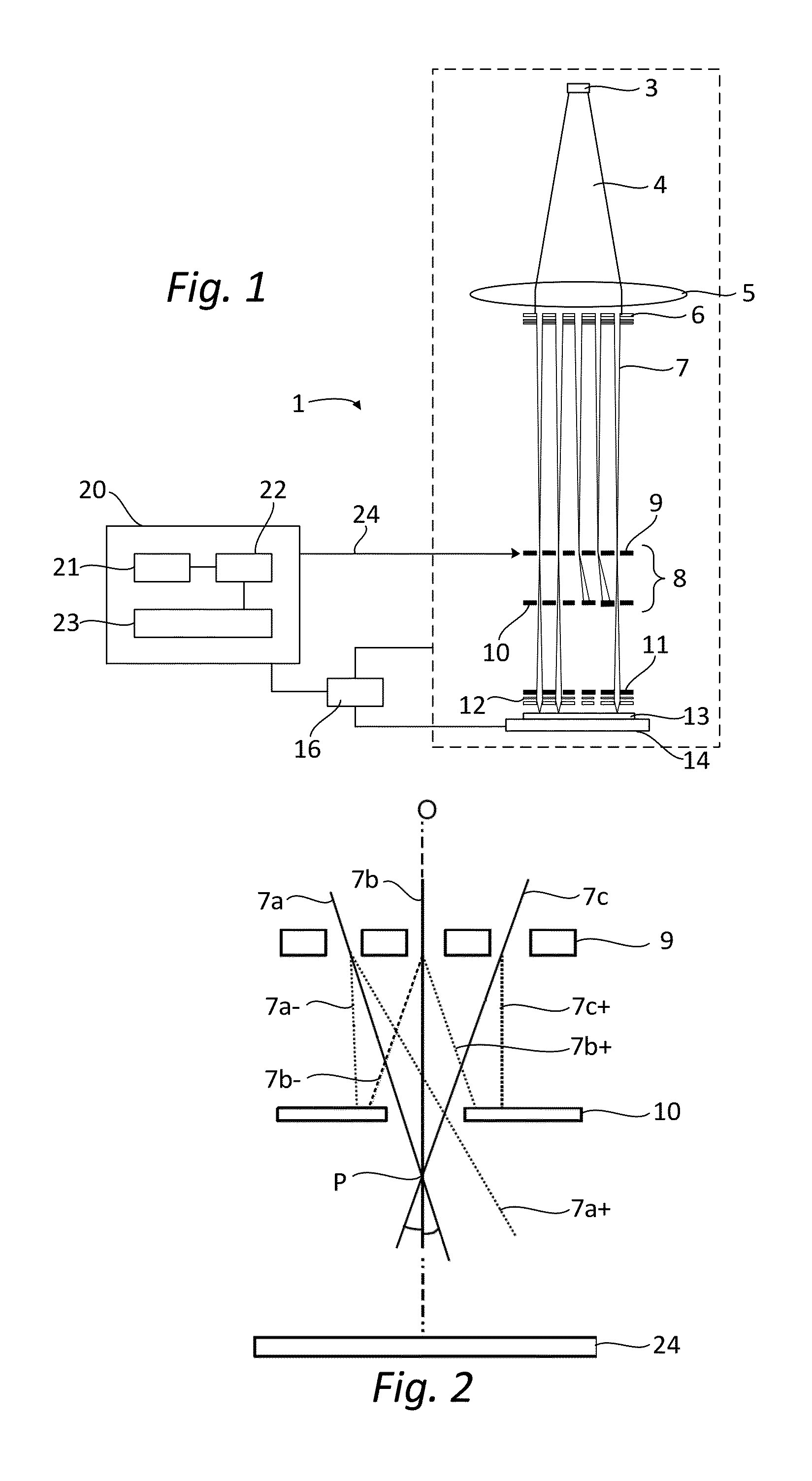
[0045]FIG. 1 shows a simplified schematic drawing of an embodiment of a charged particle multi-beamlet lithography system 1. The lithography system 1 suitably comprises a beamlet generator generating a plurality of beamlets, a beamlet modulator patterning the beamlets to form modulated beamlets, and a beamlet projector for projecting the modulated beamlets onto a surface of a target.

[0046]The beamlet generator typically comprises a source and at least one beam splitter. The source in FIG. 1 is an electron source 3 arranged to produce a substantially homogeneous, expanding electron beam 4. The beam energy of the electron beam 4 is preferably maintained relatively low in the range of about 1 to 10 keV. To achieve this, the acceleration voltage is preferably low, and...


PUM

PropertyMeasurementUnit
beam energyaaaaaaaaaa
voltageaaaaaaaaaa
diameteraaaaaaaaaa

Abstract

A method of forming an optical fiber array. The method comprises providing a substrate having a first surface and an opposing second surface. The substrate is provided with a plurality of apertures extending through the substrate from the first surface to the second surface. Additionally, a plurality of fibers is provided. The fibers have fiber ends with a diameter smaller than the smallest diameter of the apertures. For each fiber, from the first surface side of the substrate, the fiber is inserted in a corresponding aperture such that the fiber end is positioned in close proximity of the second surface. Then the fiber is bent in a predetermined direction such that the fiber abuts a side wall of the aperture at a predetermined position. Finally, the bent fibers are bonded together using an adhesive material.

Description

BACKGROUND OF THE INVENTION[0001]1. Field of the Invention[0002]The invention relates to an arrangement of optical fibers. The invention further relates to a method of forming an optical fiber array. Finally, the invention relates to a modulation device and a lithographic apparatus comprising such arrangement.[0003]2. Description of the Related Art[0004]Charged particle multi-beamlet systems are known in the art, for example from U.S. Pat. No. 6,958,804 and / or from WO2009 / 127659, both in the name of the applicant, the latter one, being specifically adapted for very high volume throughput operation. Such lithography system uses a plurality of charged particle beamlets to transfer a pattern to a target surface. The system may operate with a continuous radiation source or with a source operating at constant frequency. Pattern data are sent by means of pattern data carrying light beams to a modulation device. The modulation device may then include light sensitive elements capable of con...

Claims


Application Information

Patent Timeline
Patent Type & Authority Patents(United States)
IPC IPC(8): G02B6/42B82Y10/00B82Y40/00G02B6/36H01J37/317
CPCH01J37/3177B82Y10/00B82Y40/00G02B6/3612Y10T156/1002H01J2237/0435H01J2237/2482G02B6/3652B32B37/1284B32B37/1292B32B37/142B32B38/0012B32B2551/00
Inventor DE BOER, GUIDOVAN MELLE, RALPHVAN DE PEUT, TEUNISDERKS, HENKSPIEGELHALDER, FREDERIK MATTHIASDERKS, ROY JOSEPHUS STEPHANUSSMULDERS, EDWIN JOHANNES THEODORUS
Owner ASML NETHERLANDS BV
Why Eureka
Try Eureka