Light-controlling device and method of manufacturing the same

a technology of light controlling device and light shielding mode, which is applied in the direction of optics, instruments, optical elements, etc., can solve the problems of reducing the effectiveness of the light controlling device during the light shielding mode, and achieve the effect of maximizing the light shielding property, negatively affecting the light transmittance of the device, and increasing the total surface area

Active Publication Date: 2015-07-28
E INK CORPORATION
View PDF7 Cites 1 Cited by
  • Summary
  • Abstract
  • Description
  • Claims
  • Application Information

AI Technical Summary

Benefits of technology

[0010]In some embodiments, the first electrode has a grooved surface with a projection of a first height and a recess with a first depth. Also, the diameter of each of the charged particles may be less than the first height and less than the first depth of the grooved surface. The grooved surface increases the total surface area of the first electrode while maintaining the size of the area on the first substrate being covered by the first electrode. The increased surface area of the first electrode allows for gathering and holding an increased amount of charged particles in comparison to the first electrode having a flat surface. Accordingly, the total amount of charged particles (e.g., concentration of the charged particles in the light-adjustment medium) in the device can be increased to maximize the light shielding property during the shielding mode without negatively affecting the light transmittance of the device during the transmissive mode.
[0011]In some embodiments, the light-controlling device includes one or more particle guidance members that are thicker (in vertical direction) and are configured to create a hollow space over the first electrode. Some portion or the entire portion of the first electrode exposed through the hollow space, serving as the surface defining the bottom of the hollow space. In cases where there is a single first electrode and a hollow space within each cell, the volume of the hollow space formed on the first electrode is substantially the same or greater than the total volume of the charged particles within the cell. In cases where multiple first electrodes with hollow spaces are disposed within each cell, the total volume of the multiple hollow spaces is substantially the same or greater than the total volume of the charged particles within the cell. Without this hollow space on the first electrode, the charged particles tend to be collected widely around the first electrode, thereby affecting (e.g., blocking, reflecting, scattering) the light passing through larger area of the device even during the transmissive mode. Lesser amount of the charged particles can be employed within the cell so that lesser area is affected the charged particles during the transmissive mode, but the reduced amount of the charged particles may reduce the effectiveness of the light-controlling device during the light shielding mode. By forming the hollow space on the first electrode, however, the charged particles within the cell can be stacked on each other and be collected within the relatively narrow hollow space without having to use lesser amount of the charged particles within the cell. In other words, the amount of the charged particles within the cell can be maintained or even be increased without having to worry about the performance of the light-controlling device in both the light transmissive mode and the light shielding mode.
[0012]In some embodiments, the hollow space is tapered such that its opening towards the second substrate is larger than the opening towards the first substrate. The larger opening towards the opposing substrate makes it easier for the charged particles to be drawn into the hollow space during when the first electrode is activated to pull the charged particles. For example, the hollow space may have sidewalls that extend at an angle of about 40° to about 80° toward the second substrate. In some embodiments, the particle guidance member has an angled surface that slopes towards the hollow space, which further aids the charged particles to move towards the hollow space when the first electrode is activated to pull the charged particles.

Problems solved by technology

Lesser amount of the charged particles can be employed within the cell so that lesser area is affected the charged particles during the transmissive mode, but the reduced amount of the charged particles may reduce the effectiveness of the light-controlling device during the light shielding mode.

Method used


Image

  • Light-controlling device and method of manufacturing the same
  • Light-controlling device and method of manufacturing the same
  • Light-controlling device and method of manufacturing the same

Examples


Embodiment Construction

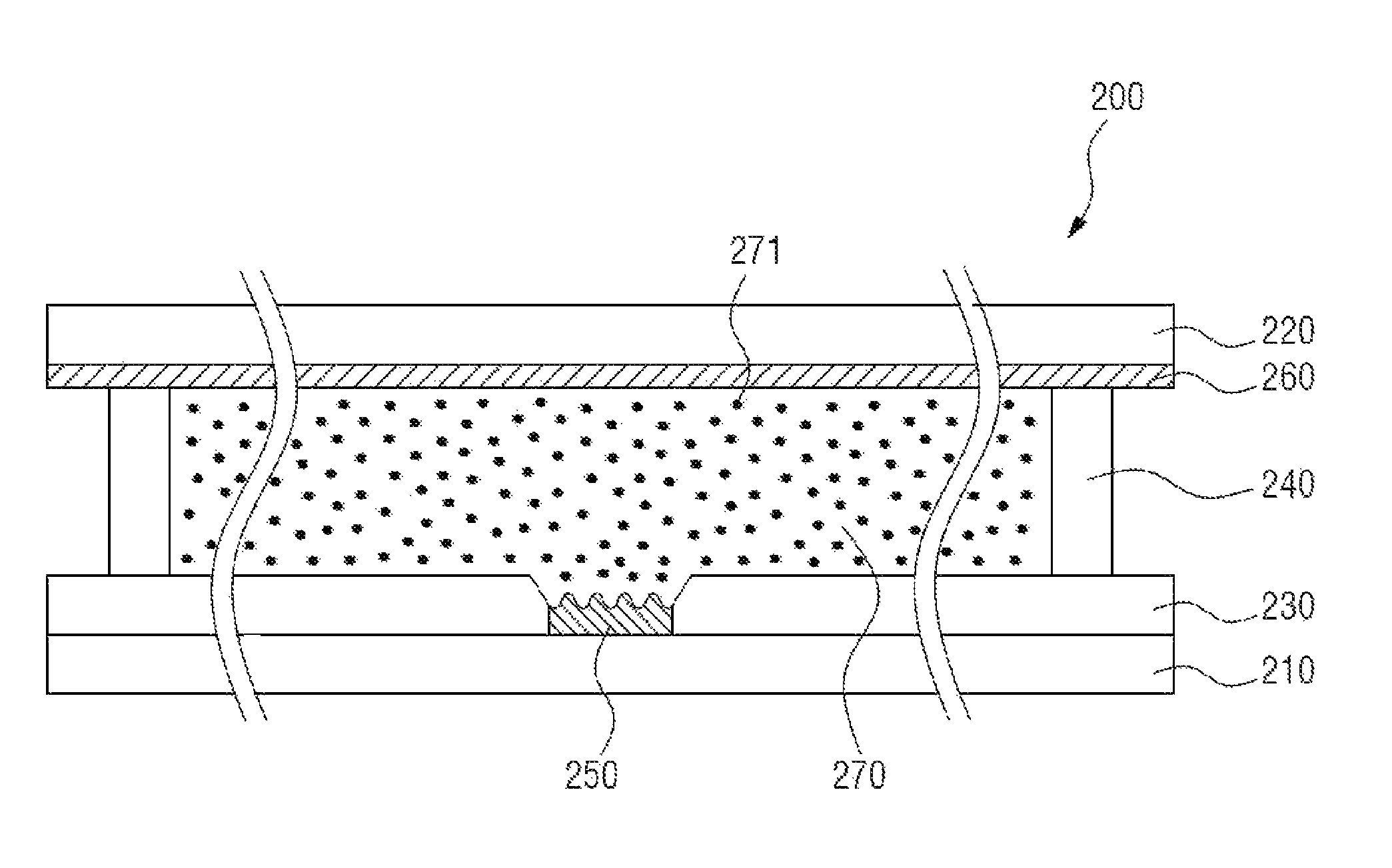
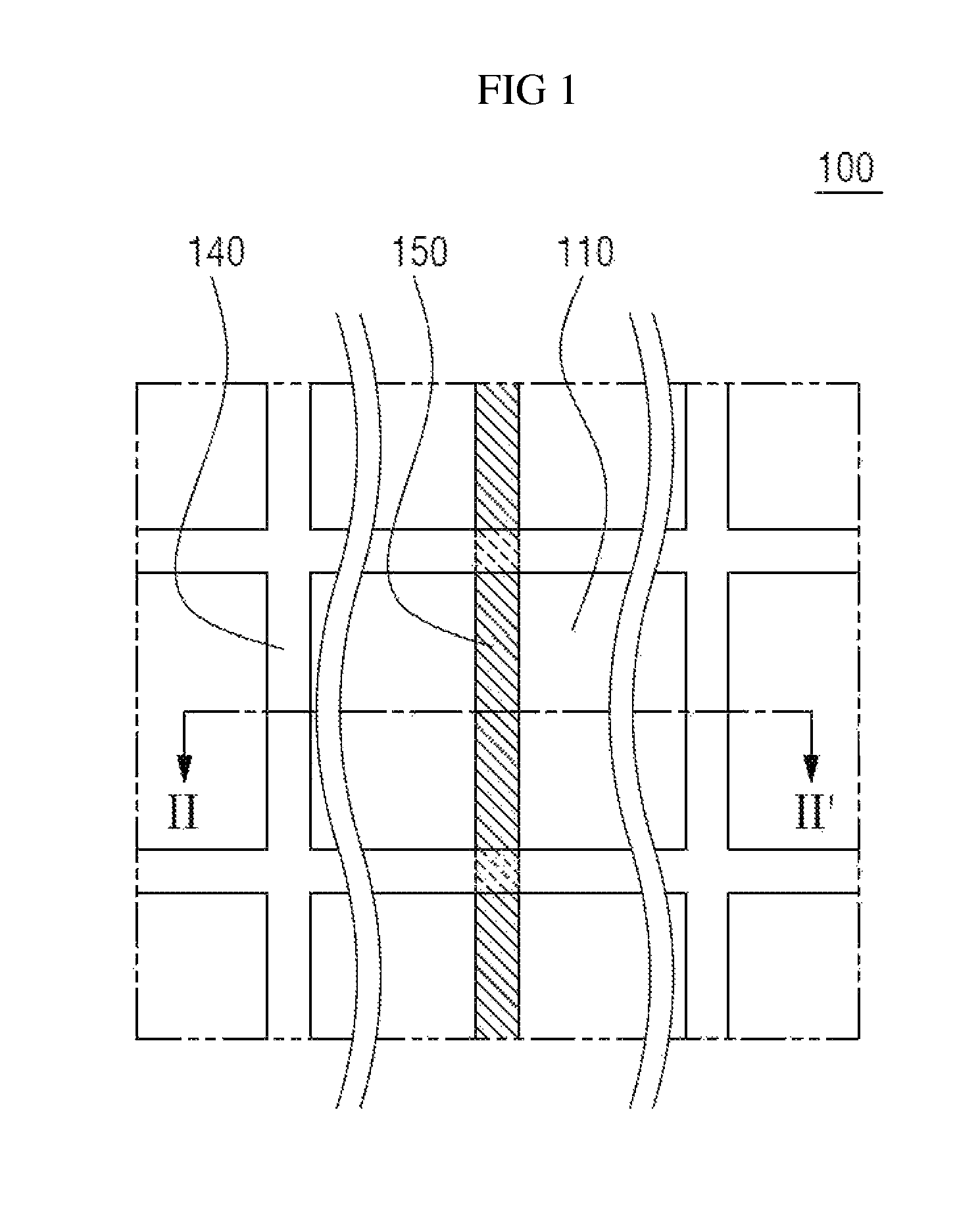
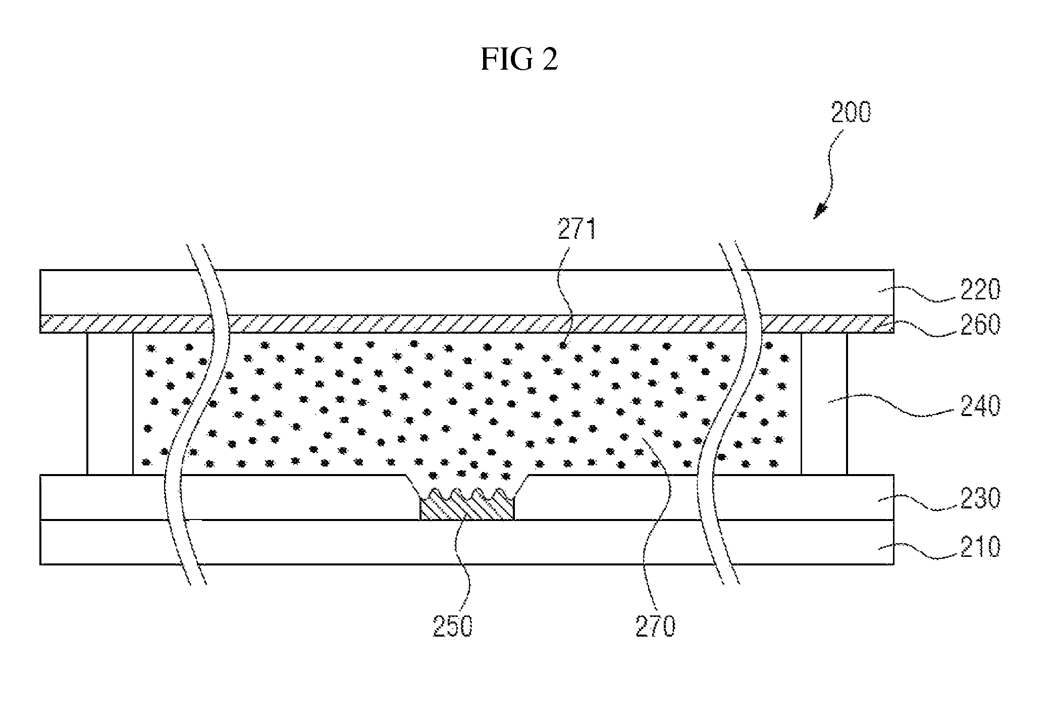
[0029]Exemplary embodiments of the present invention will be described in detail below with reference to the accompanying drawings. While the present invention is shown and described in connection with exemplary embodiments thereof, it will be apparent to those skilled in the art that various modifications can be made without departing from the spirit and scope of the invention. It should be understood that the dimensions of the elements shown in the drawings may have been exaggerated for easier explanation of the embodiments and are not intended to limit the scope of the present invention.

[0030]An element or layer formed “on” another element or layer includes all a case in which an element is directly formed on another element, and a case in which an element is formed on another element with an additional element or layer formed therebetween. Although the terms first, second, etc. may be used to describe various elements, it should be understood that these elements are not limited ...


PUM

PropertyMeasurementUnit
thicknessaaaaaaaaaa
thicknessaaaaaaaaaa
angleaaaaaaaaaa

Abstract

The light-controlling device includes a first substrate, a second substrate and a partition wall separating the first and second substrates to define a cell. A light-adjustment medium containing a plurality of charged particles is disposed between the first and second substrates. One of the first electrode on the first substrate and the second electrode on the second substrate covers lesser area of the light-controlling device than the other electrode. The electrode covering lesser area of the light-controlling device may have grooved surface to increase the surface area without increasing the overall area of the light-controlling device covered by the electrode. Particle guidance member can be used to create a reservoir for holding increased amount of charged particles on the electrode covering lesser area of the light-controlling device.

Description

CROSS-REFERENCE TO RELATED APPLICATION[0001]This application claims priority to and the benefit of Korean Patent Application No. 2012-0144974, filed on Dec. 12, 2012, the disclosure of which is incorporated herein by reference in its entirety.BACKGROUND[0002]1. Field of the Invention[0003]The present invention relates to a light-controlling device, and more particularly, to a light-controlling device with increased light transmittance and a shielding rate, and method of increasing the light transmittance and shielding rate in such a light-controlling devices.[0004]2. Discussion of Related Art[0005]Research has been conducted on a light-controlling device that may be applied to windows, automobiles, airplanes, optical devices, or image display devices to control light transmittance or reflectance. The light-controlling device may block, reflect, scatter, or transmit light in an ultraviolet (UV) region, a visible light region, or a near-infrared (NIR) region due to the characteristics...

Claims


Application Information

Patent Timeline
Patent Type & Authority Patents(United States)
IPC IPC(8): G02B26/00G02B26/08G02F1/167G02F1/16756G02F1/1676G02F1/16766
CPCG02F1/167G02F2001/1676Y10T29/49117G02F1/1676G02F1/16766G02F1/16756G02F1/1685
Inventor SEONG, MIRYNNOH, YOUNGHOONLEE, MOON SUN
Owner E INK CORPORATION
Why Eureka
Try Eureka