
Airbag

a technology of airbags and airbags, applied in the field of airbags, can solve the problems of poor airflow to the lower air chamber, and achieve the effect of great resistance for

Active Publication Date: 2015-08-04
NIHON PLAST CO LTD
View PDF20 Cites 3 Cited by
  • Summary
  • Abstract
  • Description
  • Claims
  • Application Information

AI Technical Summary

Benefits of technology

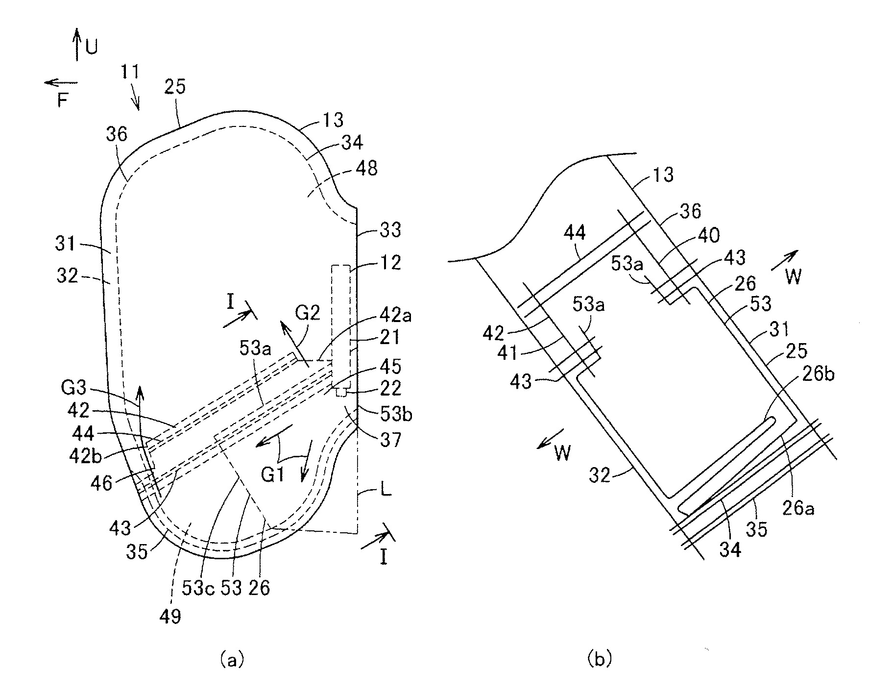
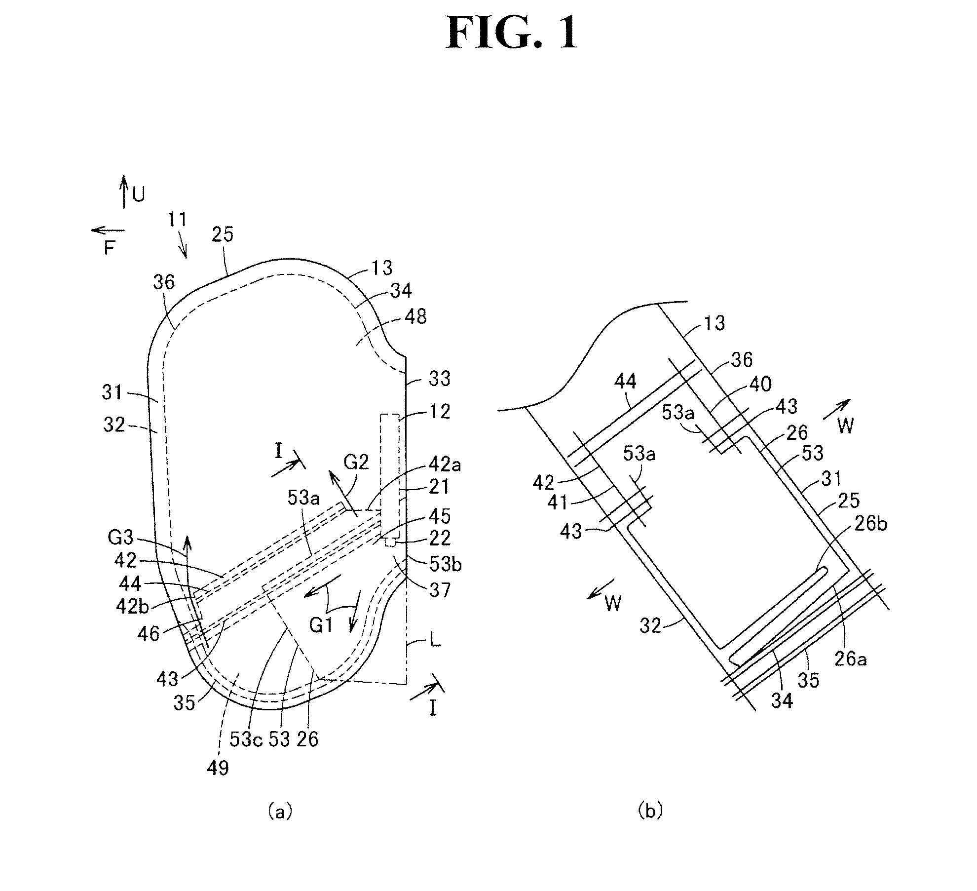
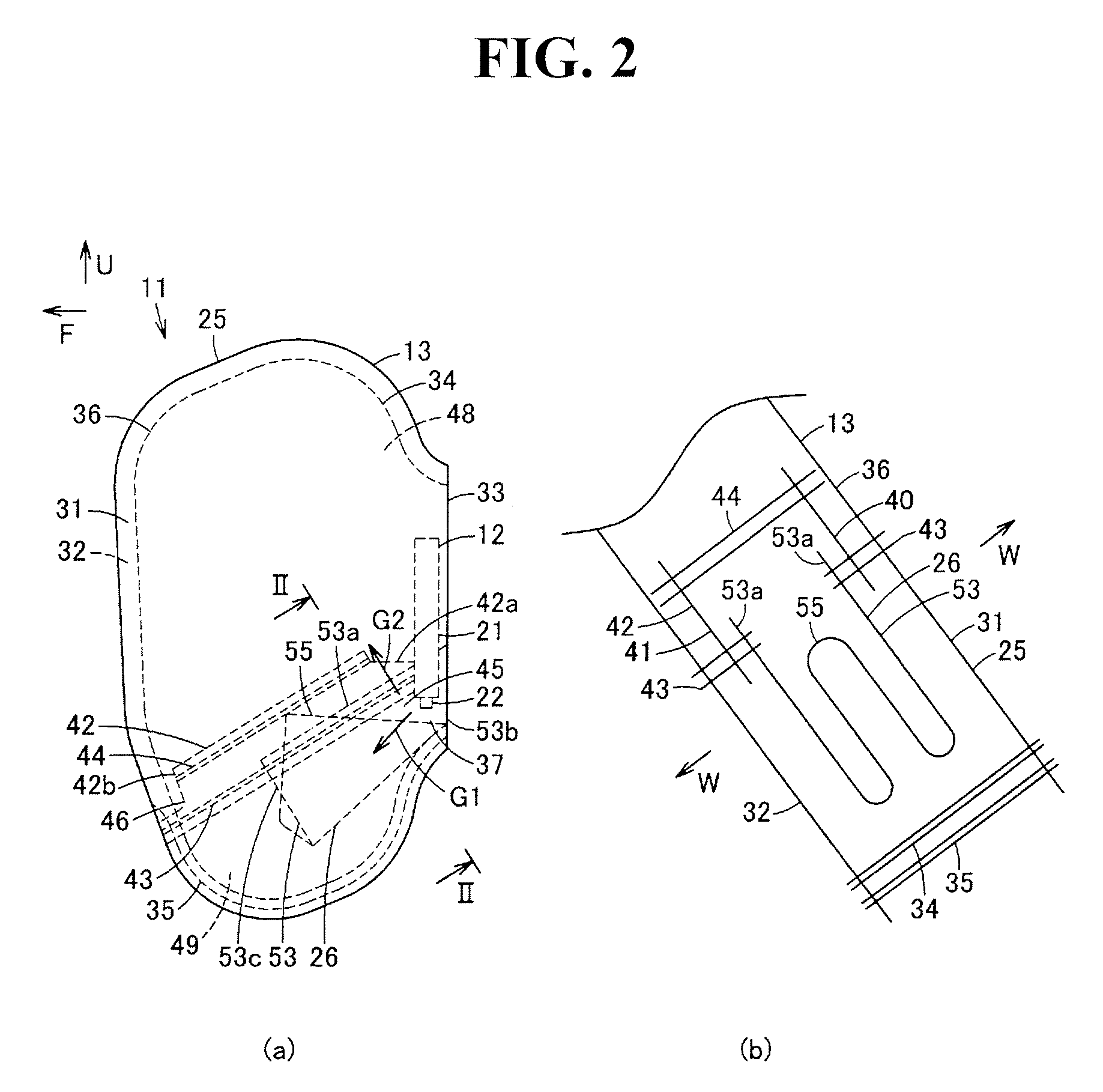
[0015]With the airbag according to the first aspect of the present invention, the reinforce member is mounted in the lower air chamber in a state in which one end part thereof is opposed to the distributing portion along the bulkhead configured to partition the airbag main body portion into the upper air chamber and the lower air chamber, the reinforce member is expanded by means of the gas introduced into the lower air chamber in the expanded state of the inflating portion of the airbag main body to thereby form a cover portion along an interior face of the lower air chamber and a redundant portion configured to slacken with respect to the interior face of the lower air chamber, and therefore, this reinforce member does not restrain a direction of the gas introduced into the lower air chamber, the flow of the gas introduced into the lower air chamber can be stabilized, the expansion behavior of the inflating portion of the airbag main body portion can be stabilized, and the interior face of the lower air chamber is reliably reinforced by means of the reinforce member and then an occupant can be stably constrained.
[0016]With the airbag according to the second aspect of the present invention, in addition to the advantageous effect of the airbag according to the first aspect of the present invention, the reinforce member are a member in which both side parts are mounted on the bulkhead of the airbag main body portion, and the intermediate part between both side parts is turned over upward in the state before expansion of the inflating portion of the airbag main body portion, whereby the reinforce member can be compactly housed in the lower air chamber.
[0017]With the airbag according to the third aspect of the present invention, in addition to the advantageous effect of the airbag according to the first aspect of the present invention, a ventilation opening that causes the upper air chamber and the lower air chamber to communicate with each other and then guides a part of the gas introduced into the lower air chamber to the upper air chamber is opened at the other end part of the airbag main body portion, whereby the gas can be reliably guided through the ventilation opening to the other end part of the upper air chamber that is spaced from a gas supply location, and the expansion behavior of the inflating portion of the airbag main portion is stabilized more significantly.
[0018]With the airbag according to the fourth aspect of the present invention, in addition to the advantageous effect of the airbag according to any one of the first to third aspects of the present invention, in the expanded state of the inflating portion of the airbag main body portion, the lower air chamber that is located on the lateral side of the waist part of the occupant is set at a higher pressure than a pressure in the upper air chamber that is located on the lateral side of the chest part of the occupant, whereby the lower air chamber is expanded with a great resistance force, the waist part with a comparatively large mass is supported speedily and reliably, and an occupant can be stably protected.

Problems solved by technology

However, in the airbag mentioned above, a gas jetted from a gas supply portion of a lower end part that is a tip end part of the inflator remains in the tube, the inflow to the lower air chamber is poor, and a gas configured to flow into the lower air chamber flows in one direction, that is, only toward a lower side, and therefore, there is a need for an additional member or the like for stabilizing an expansion behavior of the airbag.

Method used


Image

  • Airbag
  • Airbag
  • Airbag

Examples


Embodiment Construction

[0022]Hereinafter, an embodiment of an airbag according to the present invention will be described with reference to the drawings.

[0023]In FIG. 1 to FIG. 3, reference numeral 11 designates an airbag device, and this airbag device 11 constitutes a so called side airbag device mounted on a seat S of an interior room in a vehicle, the seat being a member targeted to be mounted, the side airbag device being configured to inflate and expand an airbag between a door (not shown) of a vehicle body, the door being opposed to an occupant A targeted to be protected, the occupant sitting in the seat S, to thereby protect the occupant A. It is to be noted that the occupant A is shown by means of a dummy object, and this occupant A constitutes a waist part A1, a chest part A2, and an abdominal part A3. In addition, as far as directions such as forward and backward, lateral, and longitudinal directions are concerned, with reference to a cruising direction of a vehicle, the arrow F of FIG. 1 indica...


PUM


Abstract

The present invention provides an airbag that is capable of stabilizing a flow of a gas introduced into a lower air chamber to thereby stabilize an expansion behavior, the air bag being capable of stably constraining an occupant. Along a bulkhead configured to partition an airbag main body portion into an upper air chamber and the lower air chamber, a patch is mounted into the lower air chamber so that a rear end part is opposed to a distributing portion. The patch is expanded by means of a gas introduced into the lower air chamber in an expanded state of an inflating portion of the airbag main body portion to thereby form a cover portion along an interior face of the lower air chamber and a redundant portion configured to slacken with respect to the interior face of the lower air chamber.

Description

CROSS REFERENCE TO RELATED APPLICATIONS[0001]This application claims priority of Japanese Patent Application No. 2012-259460 filed on Nov. 28, 2012. The contents of this application are incorporated herein by reference in their entirety.BACKGROUND OF THE INVENTION[0002]1. Field of the Invention[0003]The present invention relates to an airbag that expands to a lateral side of a seated occupant by means of gas introduction.[0004]2. Description of the Related Art[0005]Conventionally, there has been known an airbag device for side impact, which expands an airbag to a lateral side of an occupant sitting in a vehicle's seat to thereby protect the occupant at the time of side face collision, for example.[0006]In addition, as an airbag device of such type, there has been known an airbag device referred to as a side airbag device that is housed in a folded state in a side part of a seat, and that is configured to inflate and expand an airbag between an occupant and a door so as to thereby pr...

Claims


Application Information

Patent Timeline
Patent Type & Authority Patents(United States)
IPC IPC(8): B60R21/233B60R21/239B60R21/231B60R21/2346
CPCB60R21/233B60R21/239B60R21/23138B60R21/2346B60R2021/23123B60R2021/23146B60R2021/23324
Inventor KOIKE, MASAHIRO
Owner NIHON PLAST CO LTD
Learn More