
Reinforcing structure for slide shutter

a technology of reinforced structure and sliding shutter, which is applied in the direction of shutters/movable grilles, door/window protective devices, wing accessories, etc., can solve the problems of guide rail fallout or damage of shutter curtain, and achieve the effect of reducing the risk of unauthorized invasion

Active Publication Date: 2012-02-02
NANGOKU SHOKUSAN KK
View PDF3 Cites 3 Cited by
  • Summary
  • Abstract
  • Description
  • Claims
  • Application Information

AI Technical Summary

Benefits of technology

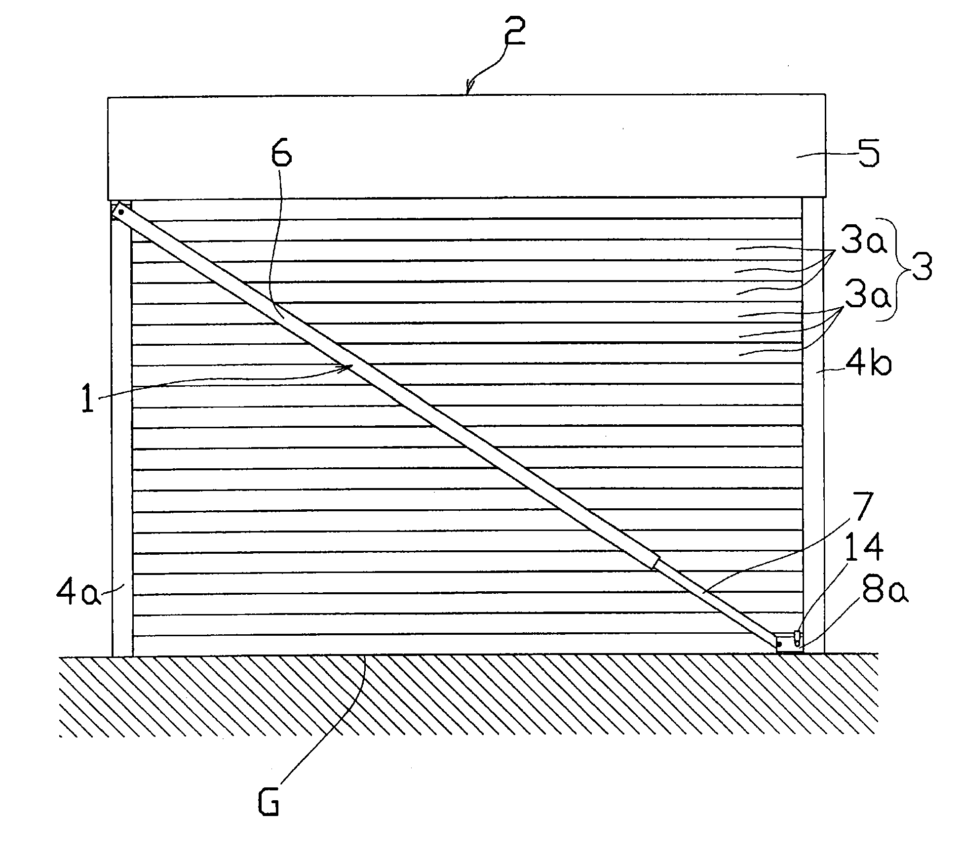
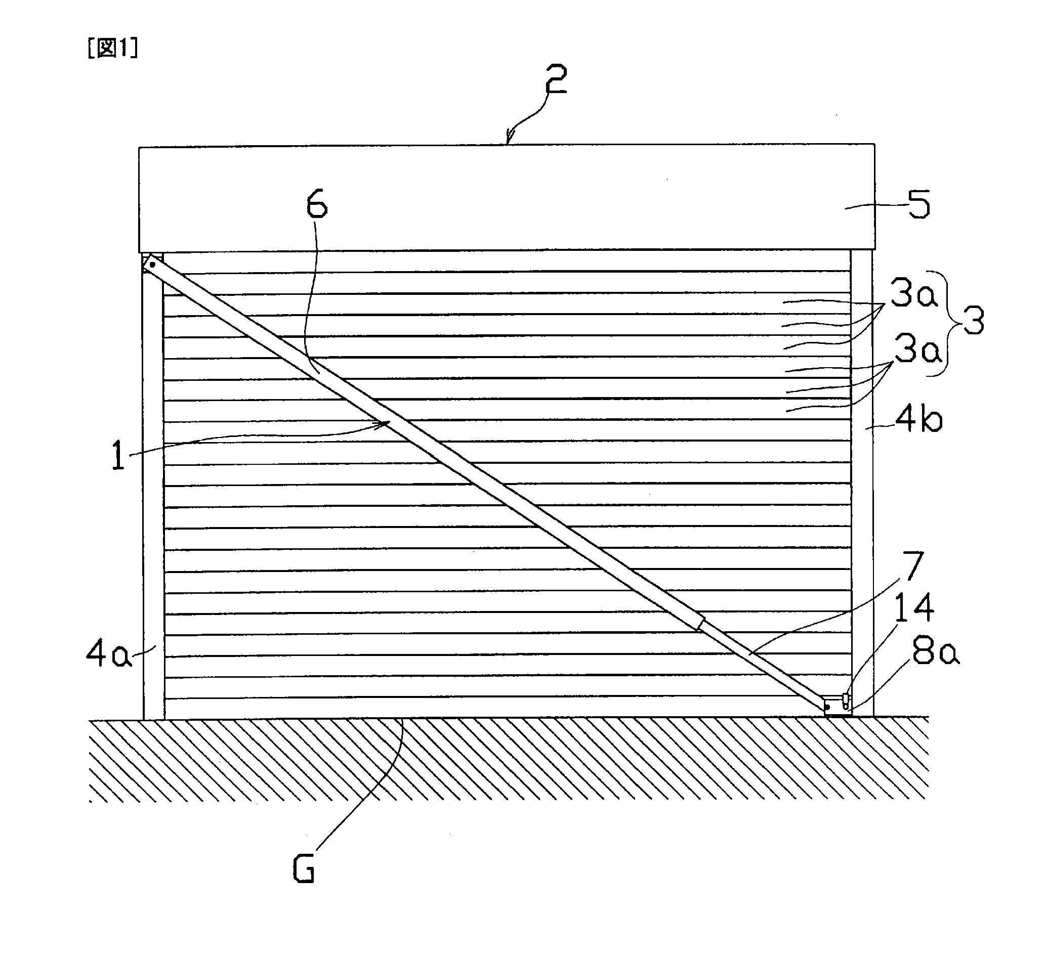
[0013]According to the reinforcing structure for the slide shutter of the present invention, the reinforcing structure includes a hollow long reinforcing base member whose one end is rotatably mounted on an upper end of one of the pair of left and right guide rails and whose other end is opened, a length-adjusting member which is inserted into the reinforcing base member and which can extend and contract, and a connecting member which is rotatably connected to a tip end of the length-adjusting member and which is attachable to and detachable from a lower end of the shutter curtain which is guided by the other guide rail and slides vertically. Therefore, when the shutter curtain is pulled down to close the slide shutter, while keeping the one end of the reinforcing base member mounted on the upper end of the one of the guide rails, the connecting member interlocks with the lowering movement of the shutter curtain and slides downward along the guide rails. Therefore, the reinforcing base member and the length-adjusting member diagonally extend from the upper end of the one guide rail to the lower end of the other guide rail and thus, it is possible to reinforce the shutter curtain which is disposed between both the guide rails.
[0014]When the shutter curtain is pulled up to open the slide shutter, the connecting member interlocks with the rising movement of the shutter curtain and slides upward along the guide rails. Therefore, since the reinforcing base member and the length-adjusting member extend between upper ends of both the guide rails, the slide shutter can be opened without closing the building opening. According to the reinforcing structure for the slide shutter of the present invention, it is possible to reliably reinforce the shutter curtain when the slide shutter is closed, and to open and close the slide shutter by the same operation as the opening and closing operations of the conventional slide shutter.
[0015]According to a reinforcing structure for a slide shutter of another embodiment, the reinforcing structure includes a hollow long first reinforcing base member whose one end is rotatably mounted on an upper end of one of the pair of guide rails and whose other end is opened, a long first length-adjusting member which is inserted into the first reinforcing base member and which can extend and contract from the first reinforcing base member, a hollow and long second reinforcing base member whose one end is rotatably mounted on an upper end of the other guide rail of the pair of guide rails and whose other end is opened, a long second length-adjusting member which is inserted into the second reinforcing base member and which can extend and contract from the second reinforcing base member, and a connecting member which rotatably connects a tip end of the first length-adjusting member and a tip end of the second length-adjusting member with each other and which is attachable to and detachable from a lower end of the slat. Therefore, like the reinforcing structure for the slide shutter of claim 1, it is possible to open and close the slide shutter by the same operation as the opening and closing operations of the conventional slide shutter. Especially according to the reinforcing structure for the slide shutter of claim 2, the first reinforcing base member and the first length-adjusting member, and the second reinforcing base member and the second length-adjusting member are disposed in substantially V-shape when the slide shutter is closed, it is possible to reinforce the shutter curtain more strongly and thus, this reinforcing structure can preferably be used for a wide slide shutter in which an intermediate position of the shutter curtain in its width direction is prone to be bent.
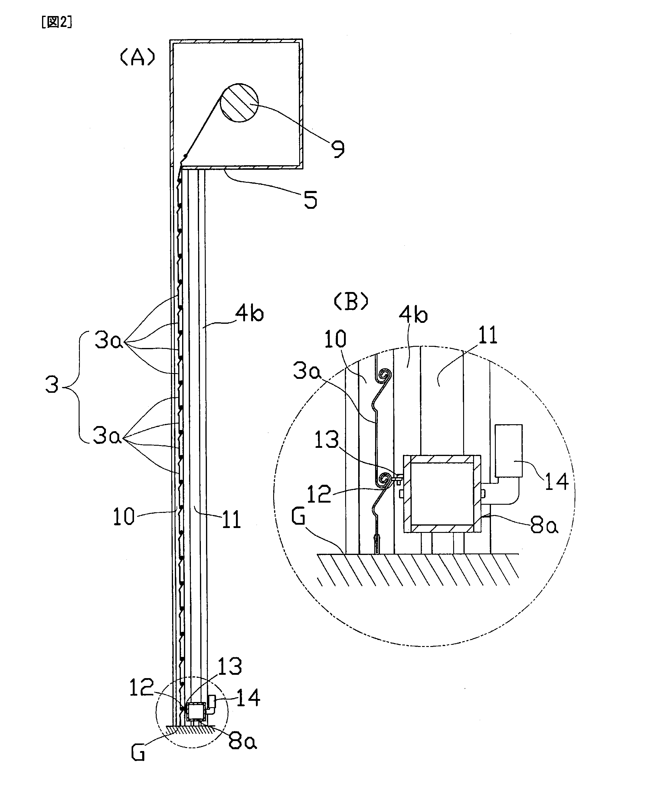
[0016]According to the reinforcing structure for the slide shutter, since the connecting member includes a fixing tool which can be fixed to a fixing hole formed in an installation surface of the slide shutter, it is possible to lock the shutter curtain by fixing the fixing tool to the fixing hole in a state where the slide shutter is closed. Therefore, it is possible to suppress the unauthorized invasion into the building where the slide shutter is disposed. Since the connecting member is fixed to the installation surface of the slide shutter and is also engaged with a lower end of the shutter curtain, it is possible to more effectively restrain the shutter curtain from being bent.
[0017]According to the reinforcing structure for the slide shutter, since the fixing tool can be engaged with an engaging hole formed in the shutter case, it is possible to pull down the shutter curtain while keeping the connecting member fixed to the upper location. As a result, the reinforcing base member and the length-adjusting member are maintained in a state where they extend between the upper ends of both the guide rails, and they do not interlock with the opening and closing operation of the slide shutter. Therefore, it is possible to reduce a load applied when the slide shutter is opened and closed.

Problems solved by technology

In the case of such a slide shutter, if strong wind blows due to bad weather such as a typhoon and a hurricane, the shutter curtain is pushed toward a room interior by wind pressure and is largely bent, and slats which configure the shutter curtain fall out from the guide rails or are damaged in some cases.

Method used


Image

  • Reinforcing structure for slide shutter
  • Reinforcing structure for slide shutter
  • Reinforcing structure for slide shutter

Examples


Embodiment Construction

[0044]A first embodiment for carrying out the present invention will be described below with reference to the drawings. As shown in FIG. 1, a reinforcing structure 1 for a slide shutter of the embodiment includes a slide shutter 2. The slide shutter 2 has a shutter curtain 3 formed by interconnecting a plurality of slats 3a, a pair of left and right guide rails 4a and 4b for vertically guiding the shutter curtain 3, and a shutter case 5 which rolls up the shutter curtain 3 at an upper location and accommodates the shutter curtain 3 therein. The reinforcing structure 1 also includes a hollow long reinforcing base member 6, one end of the reinforcing base member 6 is turnably mounted on an upper end of the guide rail 4a and the other end of the reinforcing base member 6 is opened. The reinforcing structure 1 also includes a length-adjusting member 7 inserted into the reinforcing base member 6 such that the length-adjusting member 7 can extend and contract, and a connecting member 8a w...


PUM


Abstract

A reinforcing structure for a slide shutter deters unauthorized entry of an intruder into a building and allows easy opening and closing of the shutter. The reinforcing structure (1) for a slide shutter has a vertically movable shutter curtain (3) formed by interconnecting slats (3a), a left and right pair of guide rails (4a, 4b) for guiding the shutter curtain (3), and a shutter case (5) into which the shutter curtain (3) is wound and contained. The reinforcing structure (1) is also provided with a shutter reinforcing base member (6) having one end rotatably mounted to the upper end of one guide rail (4a) and the other end open, a length adjusting member (7) inserted in the shutter reinforcing base member (6), and a connecting member (8a) rotatably connected to the front end of the length adjusting member (7), vertically sliding while being guided by the other guide rail (4b), and capable of being removably mounted to the shutter curtain (3).

Description

TECHNICAL FIELD[0001]The present invention relates to a reinforcing structure for a slide shutter, and more particularly, to a reinforcing structure for a slide shutter capable of interlocking with up-and-down movement of a shutter curtain of the slide shutter.BACKGROUND ART[0002]A slide shutter provided at an opening such as a window and a door of a building includes a shutter curtain which is guided by a pair of guide rails provided on both sides of the opening of the building and which opens and closes the opening in the vertical direction. The slide shutter usually includes a shutter case at an upper portion of the opening of the building for rolling up and accommodating the shutter curtain therein. In the case of such a slide shutter, if strong wind blows due to bad weather such as a typhoon and a hurricane, the shutter curtain is pushed toward a room interior by wind pressure and is largely bent, and slats which configure the shutter curtain fall out from the guide rails or ar...

Claims


Application Information

Patent Timeline
Patent Type & Authority Applications(United States)
IPC IPC(8): E06B9/02
CPCE05B65/0021E05C19/003E06B2009/1516E06B2009/005E06B2009/135E06B9/17
Inventor SAWADA, KATSUYA
Owner NANGOKU SHOKUSAN KK
Learn More