
Revolving frame of construction machine

Active Publication Date: 2013-08-29
HITACHI CONSTR MASCH CO LTD
View PDF6 Cites 2 Cited by
  • Summary
  • Abstract
  • Description
  • Claims
  • Application Information

AI Technical Summary

Benefits of technology

The present invention provides a revolving frame for a construction machine with improved strength to stably support the working mechanism without increasing the plate thickness dimension. The front plate, vertical plates, and reinforcing members form a firm support structural body against the working mechanism. The reinforcing members also prevent inhibition of the vertical plates caused by the sway of the working mechanism, suppress rusting, and ensure strength over a long time. The onboard equipment can also be reinforced by the reinforcing members to ensure the strength of the front plate and the entire machine. The rear sides of the boom cylinder mounting portions can also be supported by the reinforcing members, ensuring reliable reception of the load acting by extension / contraction of the boom cylinder.

Problems solved by technology

As a result, the weight of the hydraulic excavator increases, and problems such as deterioration of working performances, a rise of a manufacturing cost and the like occur.

Method used


Image

  • Revolving frame of construction machine
  • Revolving frame of construction machine
  • Revolving frame of construction machine

Examples


Embodiment Construction

[0033]An embodiment of a revolving frame of a construction machine according to the present invention will be in detail explained with reference to the accompanying drawings by taking a case in which the revolving frame of a construction machine is applied to a hydraulic excavator provided with a crawler-type lower traveling structure.

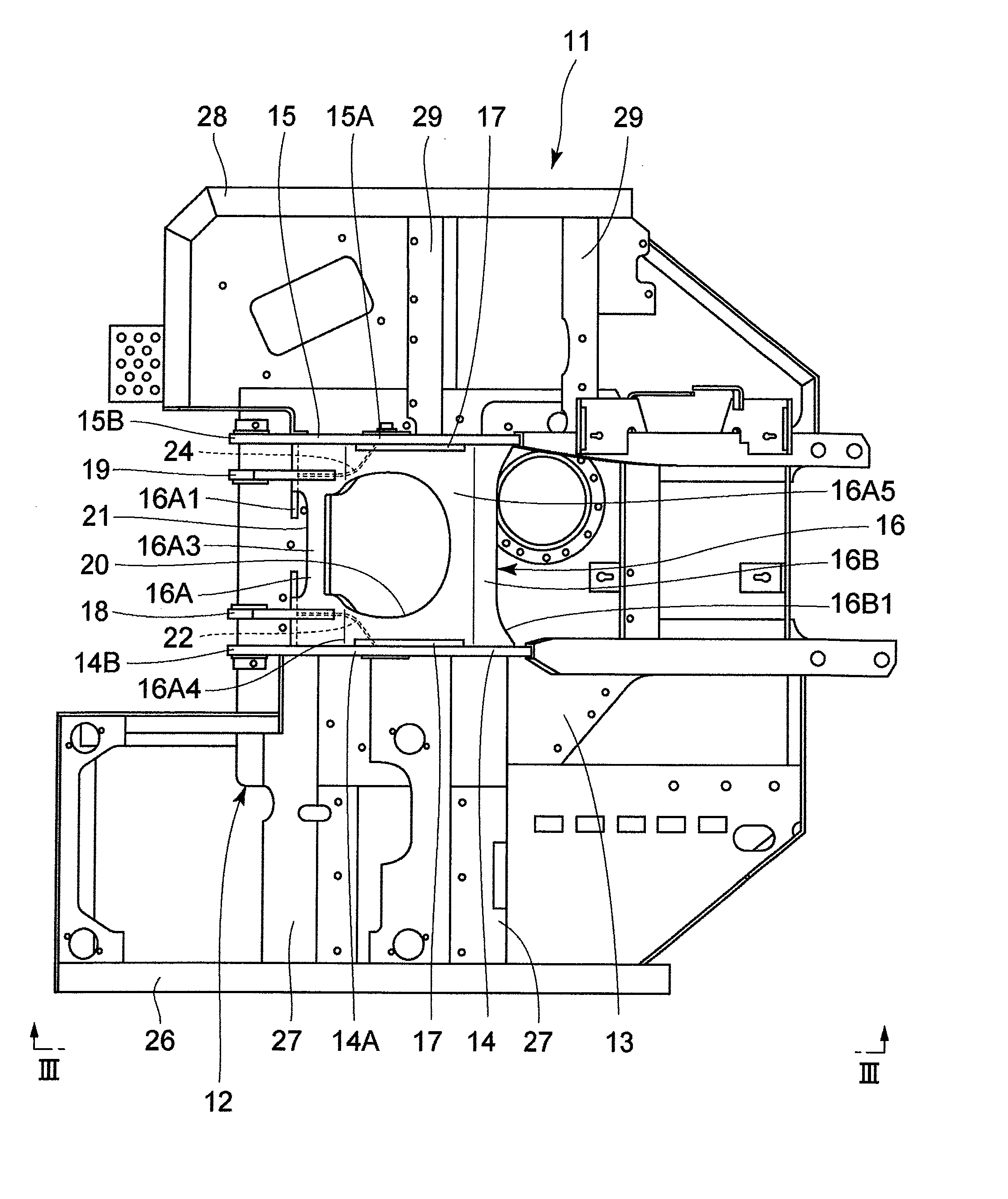
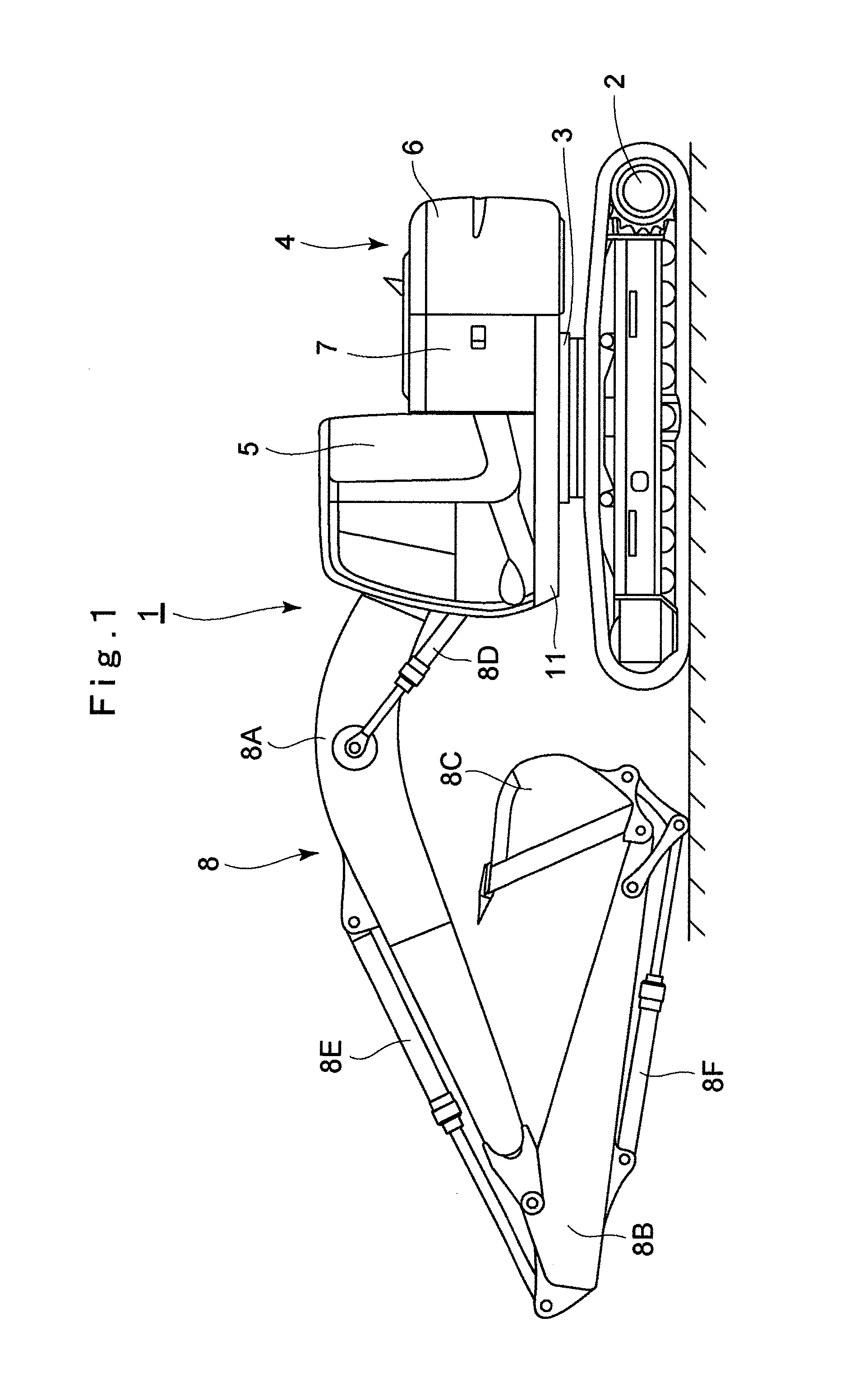
[0034]In figures, designated at 1 is a hydraulic excavator as a typical example of the construction machine. This hydraulic excavator 1 includes an automotive crawler-type lower traveling structure 2, an upper revolving structure 4 that is rotatably mounted on the lower traveling structure 2 through a revolving device 3, and a working mechanism 8 provided on the front side of the upper revolving structure 4, which will be described hereinafter.

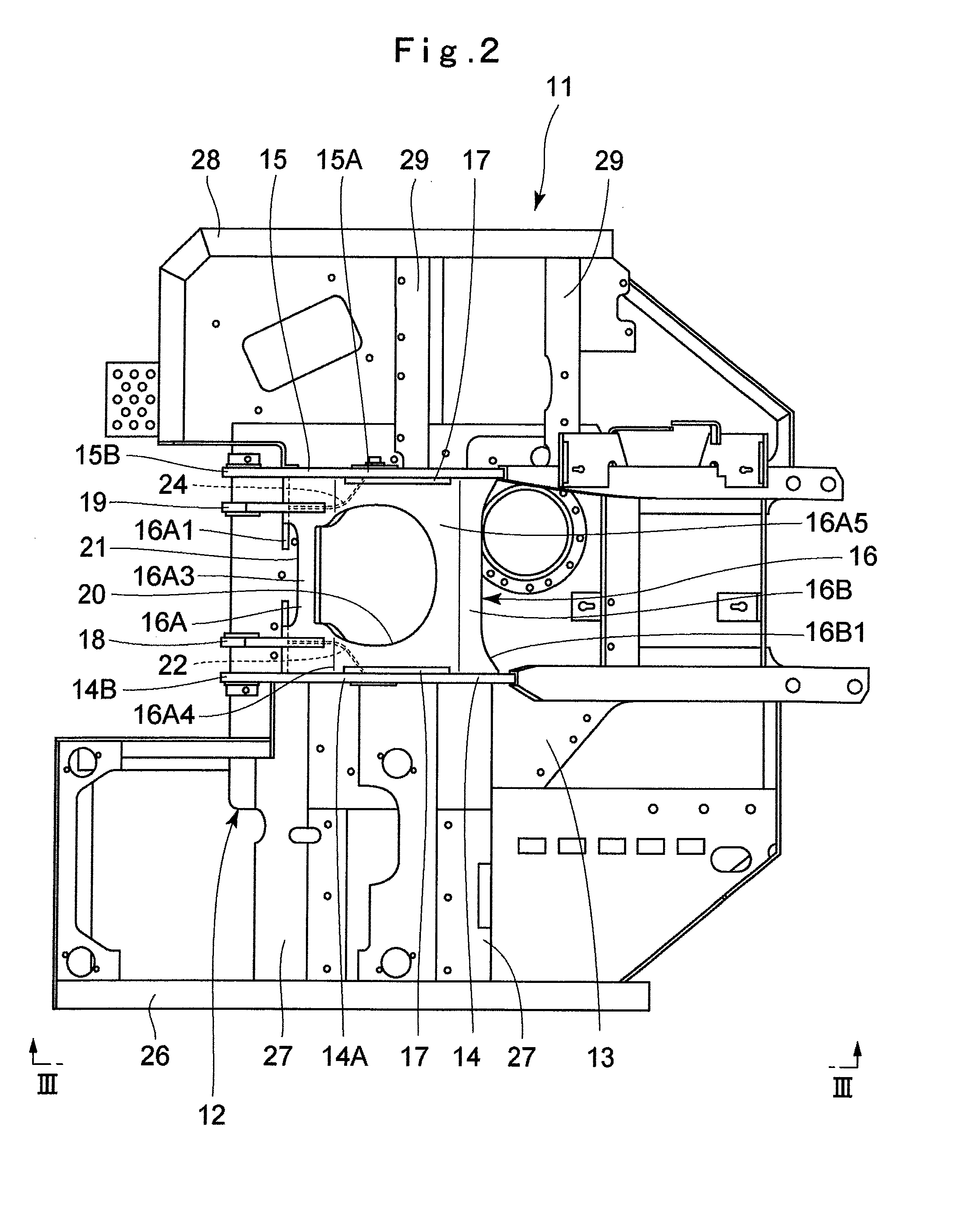
[0035]Here, as illustrated in FIGS. 1 and 2, the upper revolving structure 4 includes a revolving frame 11 which becomes a base and will be described later, a cab 5 provided on the front left side of the revolvin...


PUM


Abstract

A revolving frame is provided with left and right vertical plates installed upright on a bottom plate, and a front plate arranged on a front side of the bottom plate and connecting the left and right vertical plates to each other. A left reinforcing plate is provided at a corner where the left vertical plate and the front plate cross each other, and a right reinforcing plate is provided at a corner where the right vertical plate and the front plate cross each other. As a result, the corner portion where the left vertical plate and the front plate cross each other is reinforced by the left reinforcing plate while a left side closed space (LS) is formed, and the corner portion where the right vertical plate and the front plate cross each other is reinforced by the right reinforcing plate while a right side closed space (RS) is formed.

Description

TECHNICAL FIELD[0001]The present invention relates to a revolving frame of a construction machine suitably used for a construction machine such as a hydraulic excavator, a hydraulic crane and the like, for example.BACKGROUND ART[0002]In general, a construction machine such as a hydraulic excavator is formed of an automotive lower traveling structure, an upper revolving structure that is rotatably mounted on the lower traveling structure through a revolving device, and a working mechanism provided on the upper revolving structure. The upper revolving structure includes a revolving frame rotatably supported on the lower traveling structure, a cab provided on the front side of the revolving frame, an engine mounted on the rear side of the revolving frame, a counterweight located on the rear side of the engine and mounted on a rear end portion of the revolving frame in order to keep a weight balance with the working mechanism and the like.[0003]The revolving frame to become the basis of...

Claims


Application Information

Patent Timeline
IPC IPC(8): E02F9/08E02F3/30
CPCB62D21/186E02F9/0816E02F9/08E02F3/30E02F9/006B62D21/18
Inventor NAKAMURA, MASAO
Owner HITACHI CONSTR MASCH CO LTD
Learn More