Systems, methods and computer-readable media for configuring receiver latency

A technology of delay time and maximum delay time, applied in the direction of time division multiplexing system, transmission system, two-way working system, etc., can solve the problems of restricting the utilization of existing media network technology, and achieve reliable reception, guaranteed reception, and easy delay the effect of time

Active Publication Date: 2010-06-09
敖联控股私人有限公司
View PDF1 Cites 28 Cited by
  • Summary
  • Abstract
  • Description
  • Claims
  • Application Information

AI Technical Summary

Problems solved by technology

[0032] These types of limitations have limited the u

Method used


Image

  • Systems, methods and computer-readable media for configuring receiver latency
  • Systems, methods and computer-readable media for configuring receiver latency
  • Systems, methods and computer-readable media for configuring receiver latency

Examples


Embodiment Construction

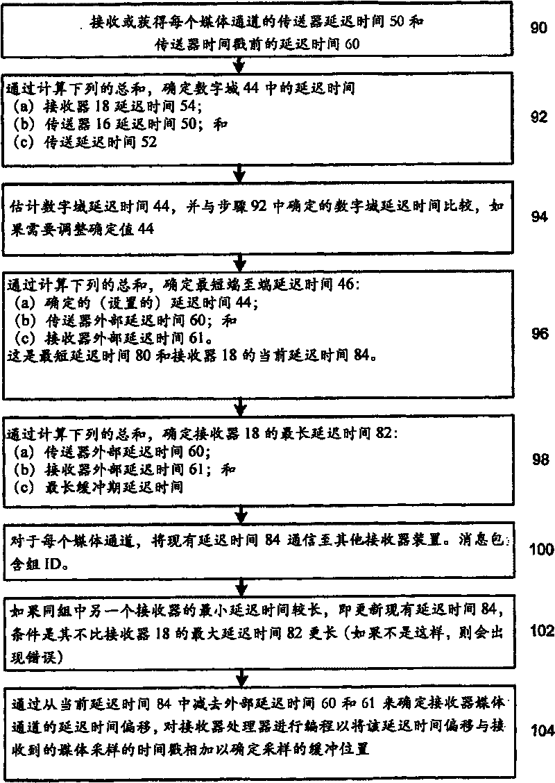
[0277] The following examples refer to Figure 7 The flowchart describes the mechanism for publishing TX delay times and agreeing receiver delay time offsets. In this example, the following assumptions are made:

[0278] - Synchronize network time of multiple participating devices.

[0279] - Transmitters timestamp their output frames / samples according to a shared notion of time.

[0280] - The receiver is able to time synchronize the output with the shared time and the timestamp of the frame or sample.

[0281] Each transmission channel has a local transmitter delay time 50 and an external delay time 60 associated therewith. These values ​​are available to the receiver 18 through entries in a shared database (eg DNS-SD). The receiver 18 should not select a delay time value less than the value 50. To determine the set time-stamped delay time 44, in step 92, the receiver delay time 50 is calculated with any other delay time available to the receiver. The sum of the values ...


PUM


Abstract

The present disclosure is related to transmitting and receiving media channels, such as audio and video channels. These channels may be transmitted as packets from one or more transmitting devices to one or more receiving devices for playout. Certain embodiments of the present disclosure include systems, methods, and computer- readable media for determining latency of a data network for synchronised playout of received signals. Additionally, certain embodiments of the present disclosure include systems, methods, and computer-readable media for synchronising playout among devices connected to a data network.

Description

[0001] priority document [0002] This application claims priority from the following applications: Australian Provisional Patent Application No. 2007902513, filed 11 May 2007, entitled "Configuring Receiver Latency" and filed 15 May 2007 Australian Provisional Patent Application No. 2007902582, entitled "Configuring Receiver Latency", was filed. Each of the above applications is incorporated herein by reference in its entirety. [0003] Cross References to Related Applications [0004] This application is related to the following co-pending applications: [0005] U.S. Patent Application Serial No. 11 / 409,190, entitled "Method for Transporting Digital Media," filed April 21, 2006; [0006] PCT Application No. PCT / AU2007 / 000668, filed May 17, 2007, entitled "Transmitting and Reciieving MediaPacket Streams"; and [0007] PCT Application No. PCT / AU2007 / 000667, filed May 17, 2007, entitled "Redundant Media Packet Streams". Each of the above applications is incorporated herein b...

Claims


Application Information

Patent Timeline
IPC IPC(8): H04N7/24H04N7/14H04N7/52
CPCH04J3/0667H04J3/0632H04N21/2368H04N21/4305H04N21/4341H04L43/0858H04L67/10H04N21/233H04N21/23406H04N21/2402H04N21/242H04N21/64322H04N21/845
Inventor 安德鲁·怀特艾丹·威廉斯
Owner 敖联控股私人有限公司
Why Eureka
Try Eureka