

Radio-wave clock
- Summary
- Abstract
- Description
- Claims
- Application Information
AI Technical Summary
Benefits of technology
Problems solved by technology
Method used
Image

Examples
Embodiment Construction
[0030] The present invention will be described in connection with preferred modes of embodiment with reference to the accompanying drawings.
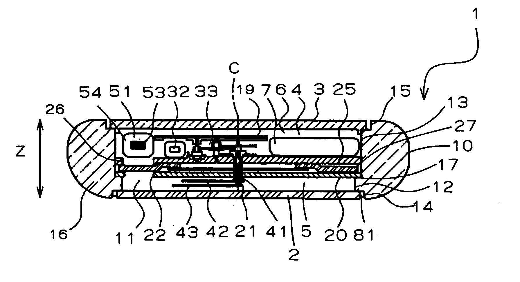
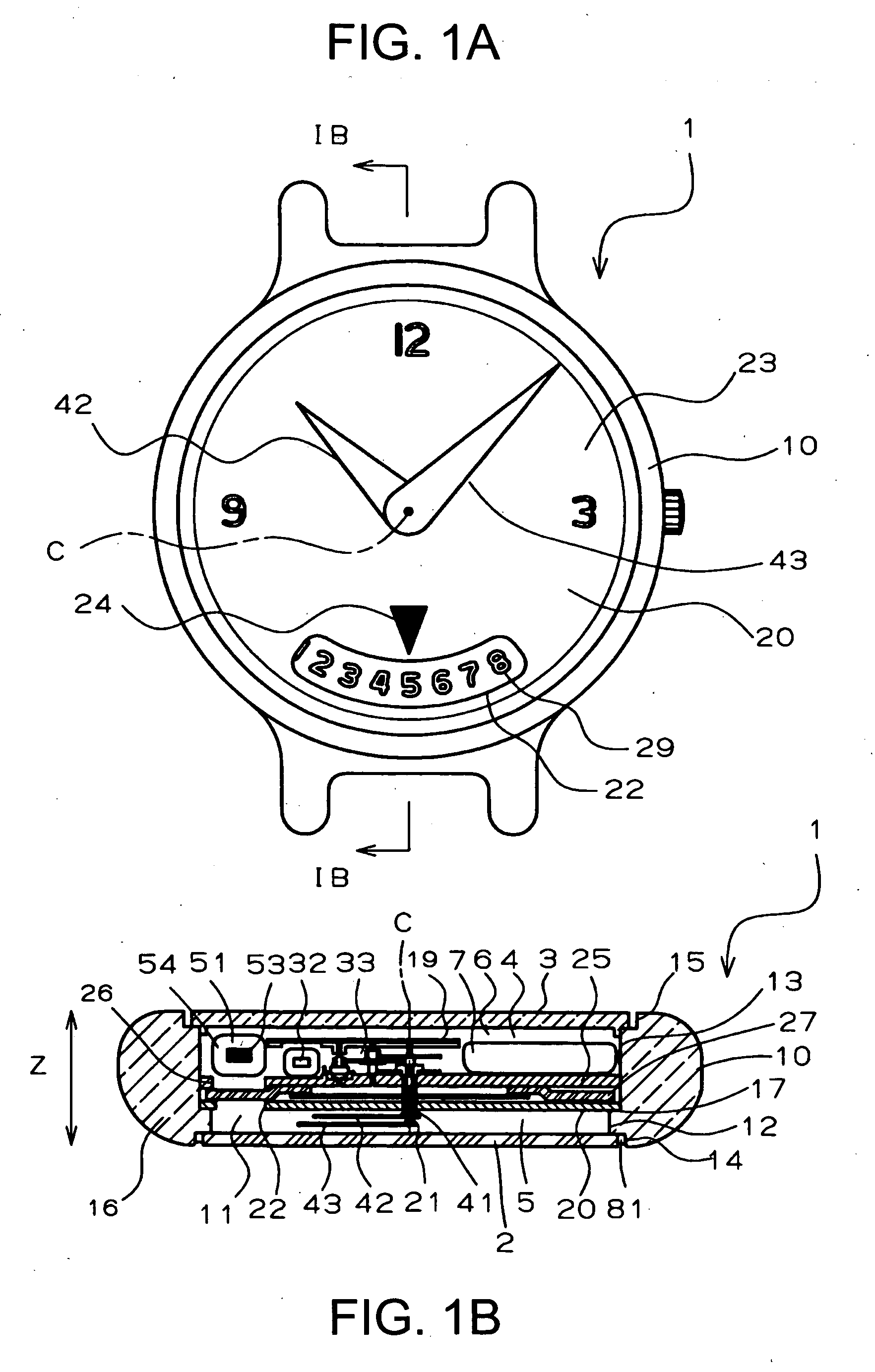
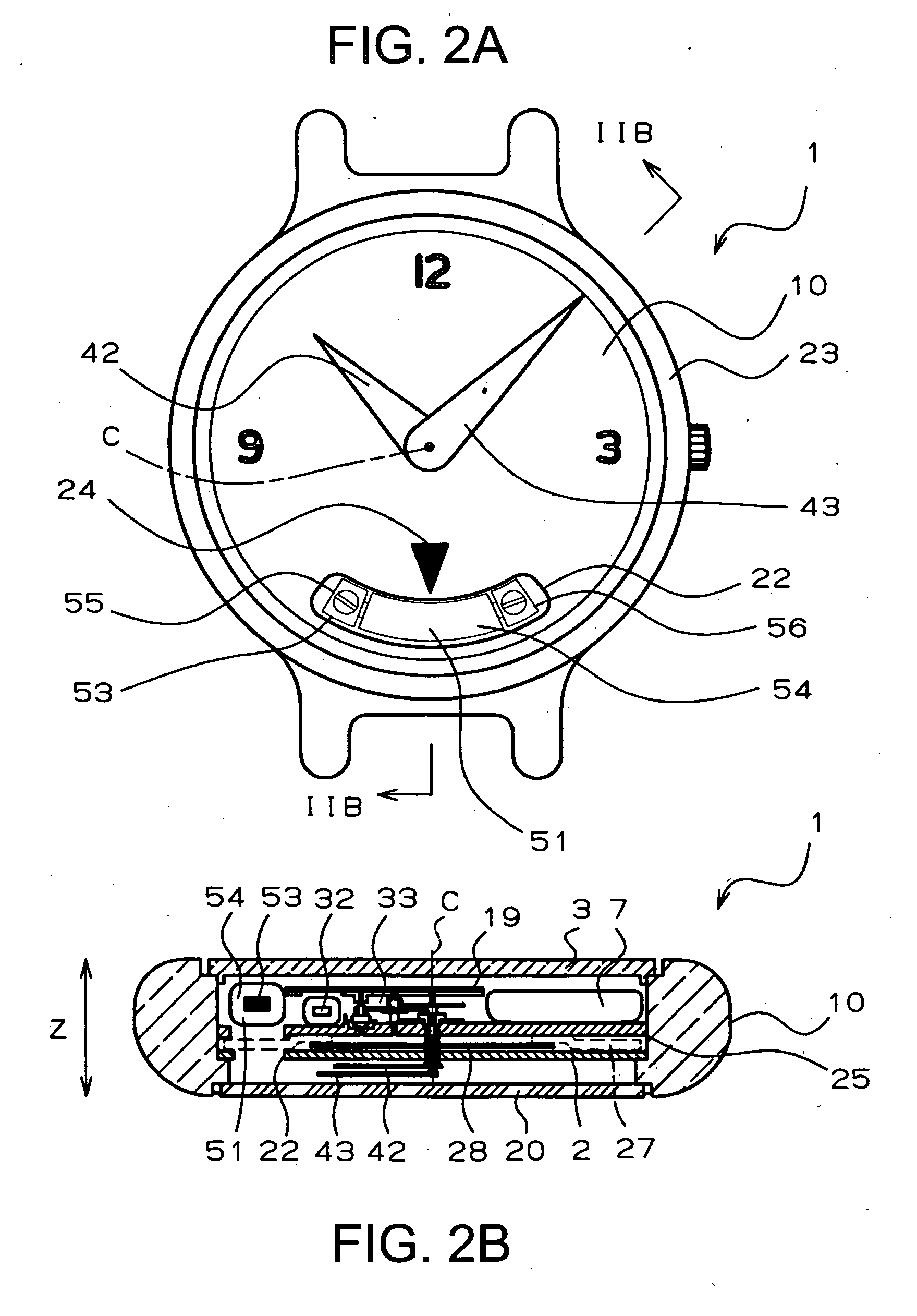
[0031] FIGS. 1 to FIGS. 3 show a radio-wave watch 1 of a first preferred embodiment according to the invention. The radio-wave watch 1 is provided, in the mode of a wrist watch, with a generally annular case 10, which has an opening 11 composed of a diametrically-small hole portion 12 on the front side and a diametrically-large hole portion 13 on the back side. A glass 2 is fitted through a packing 81 in a diametrically-large annular groove portion 14 on the open end of the diametrically-small hole portion 12, and a case back 3 is screwed in the open end 15 of the diametrically-large hole portion 13. As a result, a chamber 4 is formed in the case 10 by the circumferential wall 16 of the case 10, the glass 2 and the case back 3.
[0032] A dial 20 made of a metallic disc is placed on a step portion 17 between the diametrically-small hole portion 1...
PUM
 Abstract
Description
Claims
Application Information