Revolving frame of construction machine

a technology of construction machine and rotating frame, which is applied in the direction of mechanical machines/dredgers, roofs, transportation and packaging, etc., can solve the problem of rising manufacturing costs

Active Publication Date: 2015-02-24
NIHON KENKI CO LTD
View PDF10 Cites 0 Cited by
  • Summary
  • Abstract
  • Description
  • Claims
  • Application Information

AI Technical Summary

Benefits of technology

[0008]In view of the above-discussed problems with the conventional art, it is an object of the present invention to provide a revolving frame of a construction machine which can stably support the working mechanism by improving the strength of the left and right vertical plates and the front plate without increasing the plate thickness dimension.
[0011]With this arrangement, a joint portion between the front plate and the left vertical plate can be reinforced by the left reinforcing member, and a joint portion between the front plate and the right vertical plate can be reinforced by the right reinforcing member. Thus, a firm support structural body against the working mechanism can be configured by the front plate, the vertical plates, and the reinforcing members without increasing the plate thickness dimension of the front plate and each of the vertical plates. As a result, a load such as an excavating reaction force and the like acting from the working mechanism can be reliably received by the vertical plates, the front plate and the like, and the working mechanism can be stably supported all the time. Moreover, by performing a work in an attitude in which the working mechanism is lifted up, for example, even if the working mechanism sways in the left or right direction, twisting deformation or the like of the vertical plate caused by the sway of this working mechanism can be suppressed.
[0014]By configuring as above, the reinforcing member forms the closed space shut at the corner portion between the rear surface of the front plate and the vertical plate, and thus, by painting the vertical plate, the front plate, and the reinforcing member from the outside, intrusion of rainwater, washing water and the like into the space surrounded by the vertical plate, the front plate, and the reinforcing plate can be suppressed. As a result, rusting on the front plate, each of the vertical plates, and each of the reinforcing members in the space can be suppressed, and strength of the front plate, each of the vertical plates, and each of the reinforcing members can be kept properly over a long time.
[0018]With this arrangement, in assembling the construction machine, the onboard equipment including a revolving motor, a control valve device and the like, for example, are inserted through the equipment passage hole provided in the front plate. In such a case, too, since the left and right reinforcing members are provided sandwiching the equipment passage hole between them, the periphery of the equipment passage hole where strength can easily deteriorate in the front plate can be reliably reinforced by the reinforcing member, and the entire strength of the front plate can be sufficiently ensured.
[0020]With this arrangement, the rear sides of the left and right second cylinder mounting portions provided on the front surface side of the front plate can be supported by the left and right reinforcing members sandwiching the front plate. As a result, a load acting by extension / contraction of the boom cylinder can be reliably received by the support structural body formed of the front plate, the vertical plates, and the reinforcing members.

Problems solved by technology

As a result, the weight of the hydraulic excavator increases, and problems such as deterioration of working performances, a rise of a manufacturing cost and the like occur.

Method used


Image

  • Revolving frame of construction machine
  • Revolving frame of construction machine
  • Revolving frame of construction machine

Examples


Embodiment Construction

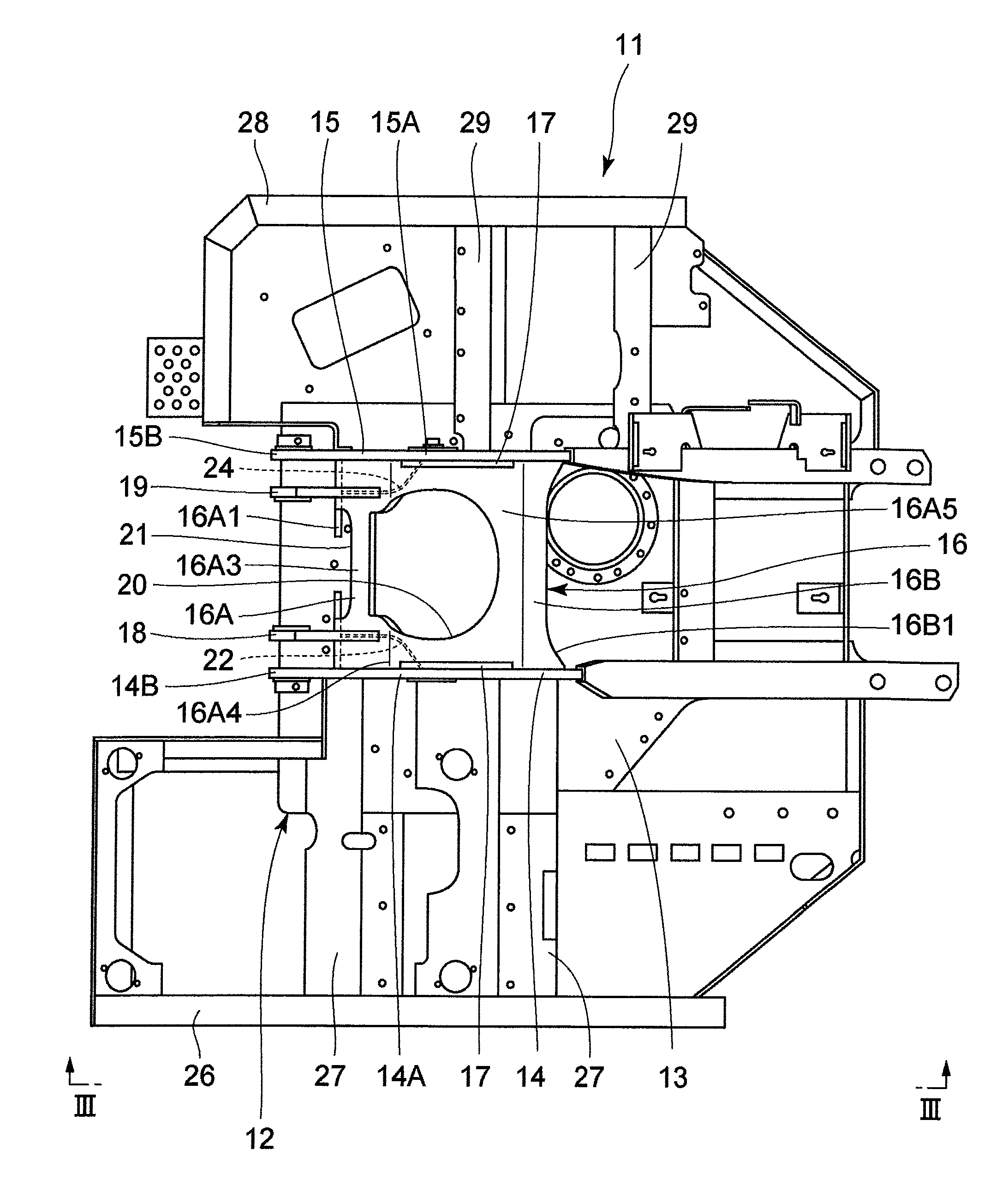
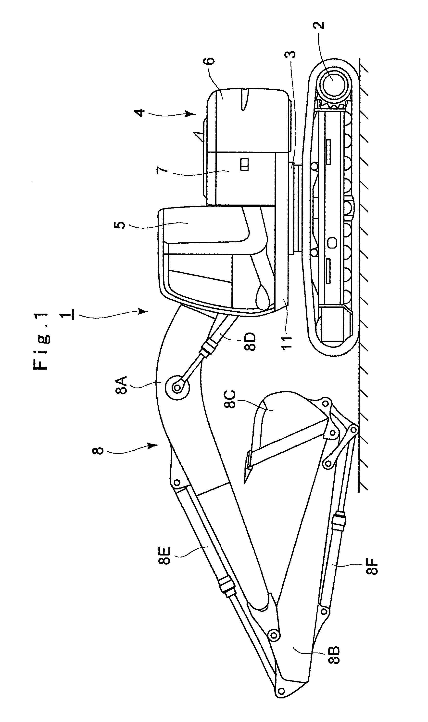
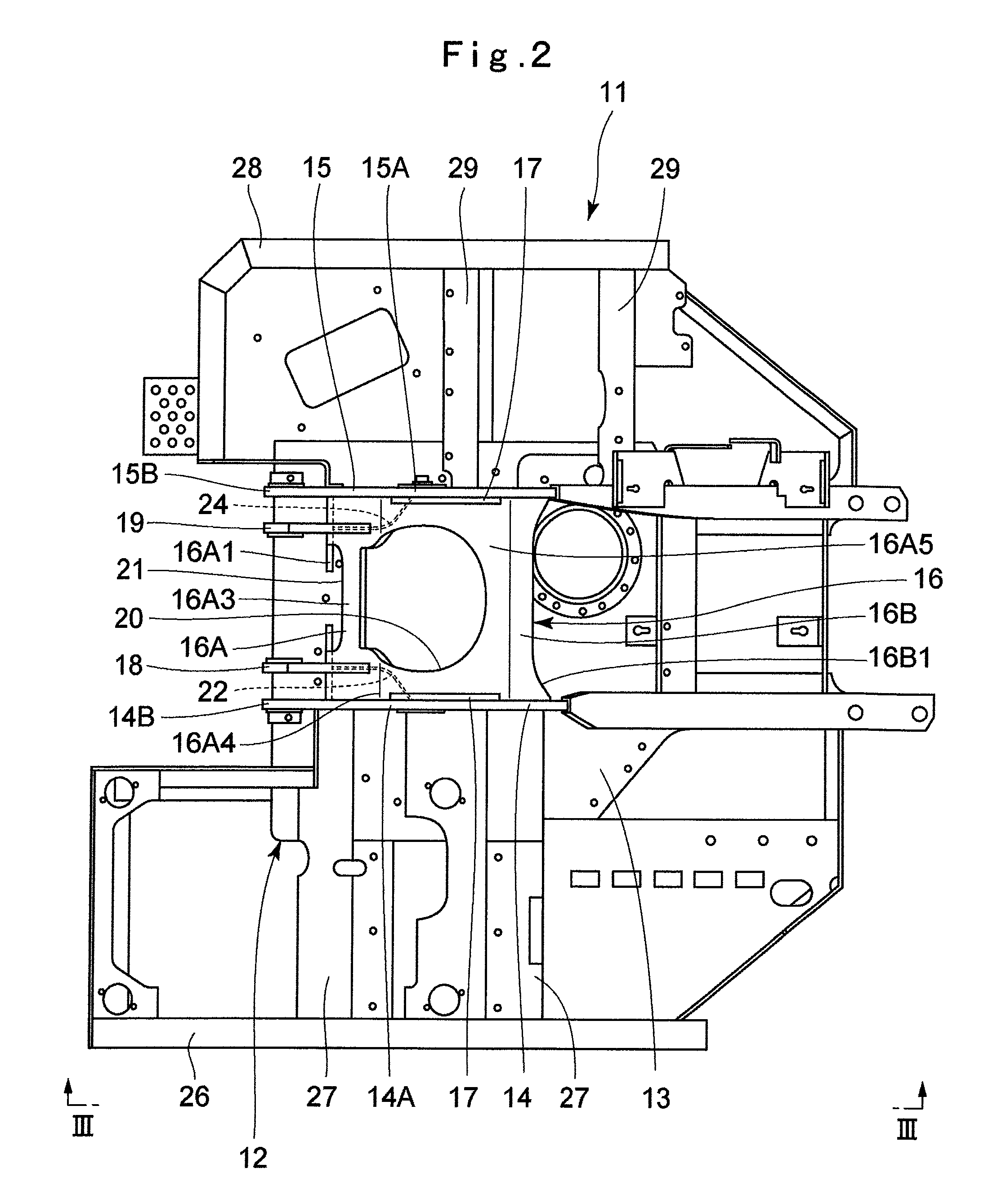
[0033]An embodiment of a revolving frame of a construction machine according to the present invention will be in detail explained with reference to the accompanying drawings by taking a case in which the revolving frame of a construction machine is applied to a hydraulic excavator provided with a crawler-type lower traveling structure.

[0034]In figures, designated at 1 is a hydraulic excavator as a typical example of the construction machine. This hydraulic excavator 1 includes an automotive crawler-type lower traveling structure 2, an upper revolving structure 4 that is rotatably mounted on the lower traveling structure 2 through a revolving device 3, and a working mechanism 8 provided on the front side of the upper revolving structure 4, which will be described hereinafter.

[0035]Here, as illustrated in FIGS. 1 and 2, the upper revolving structure 4 includes a revolving frame 11 which becomes a base and will be described later, a cab 5 provided on the front left side of the revolvin...


PUM


Abstract

A revolving frame is provided with left and right vertical plates installed upright on a bottom plate, and a front plate arranged on a front side of the bottom plate and connecting the left and right vertical plates to each other. A left reinforcing plate is provided at a corner where the left vertical plate and the front plate cross each other, and a right reinforcing plate is provided at a corner where the right vertical plate and the front plate cross each other. As a result, the corner portion where the left vertical plate and the front plate cross each other is reinforced by the left reinforcing plate while a left side closed space (LS) is formed, and the corner portion where the right vertical plate and the front plate cross each other is reinforced by the right reinforcing plate while a right side closed space (RS) is formed.

Description

TECHNICAL FIELD[0001]The present invention relates to a revolving frame of a construction machine suitably used for a construction machine such as a hydraulic excavator, a hydraulic crane and the like, for example.BACKGROUND ART[0002]In general, a construction machine such as a hydraulic excavator is formed of an automotive lower traveling structure, an upper revolving structure that is rotatably mounted on the lower traveling structure through a revolving device, and a working mechanism provided on the upper revolving structure. The upper revolving structure includes a revolving frame rotatably supported on the lower traveling structure, a cab provided on the front side of the revolving frame, an engine mounted on the rear side of the revolving frame, a counterweight located on the rear side of the engine and mounted on a rear end portion of the revolving frame in order to keep a weight balance with the working mechanism and the like.[0003]The revolving frame to become the basis of...

Claims


Application Information

Patent Timeline
Patent Type & Authority Patents(United States)
IPC IPC(8): B62D25/10E02F9/08E02F3/30B62D21/18E02F9/00
CPCE02F9/08B62D21/186E02F9/0816E02F3/30E02F9/006B62D21/18
Inventor NAKAMURA, MASAO
Owner NIHON KENKI CO LTD
Why Eureka
Try Eureka