
System and method for a radio frequency switch

a radio frequency switch and system technology, applied in the field of radio frequency circuits and methods, can solve problems such as leakage of distortion products created in the transmitter into the receive path, increase the design complexity of mobile phones,

Inactive Publication Date: 2015-08-04
INFINEON TECH AG
View PDF16 Cites 16 Cited by
  • Summary
  • Abstract
  • Description
  • Claims
  • Application Information

AI Technical Summary

Benefits of technology

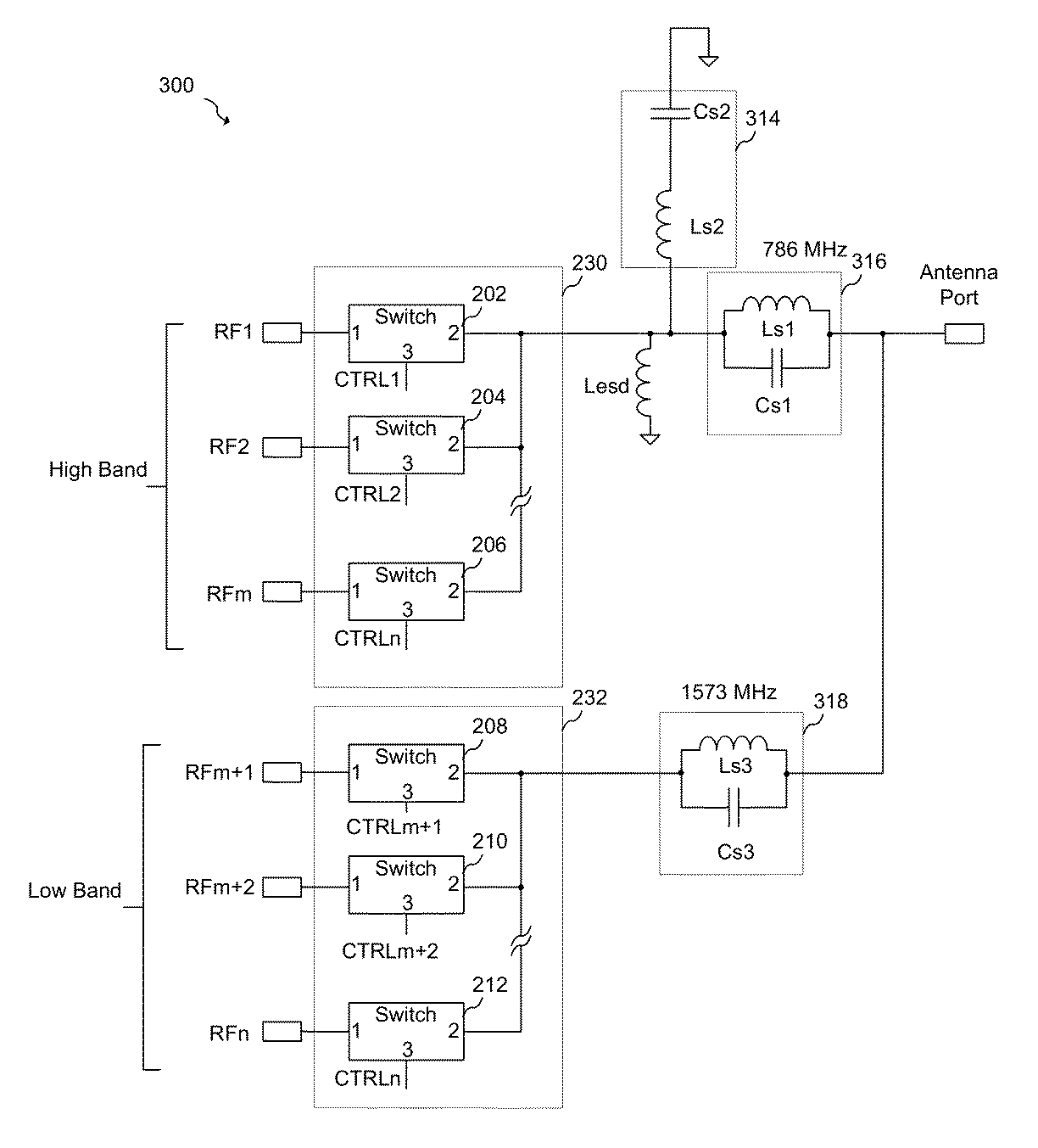
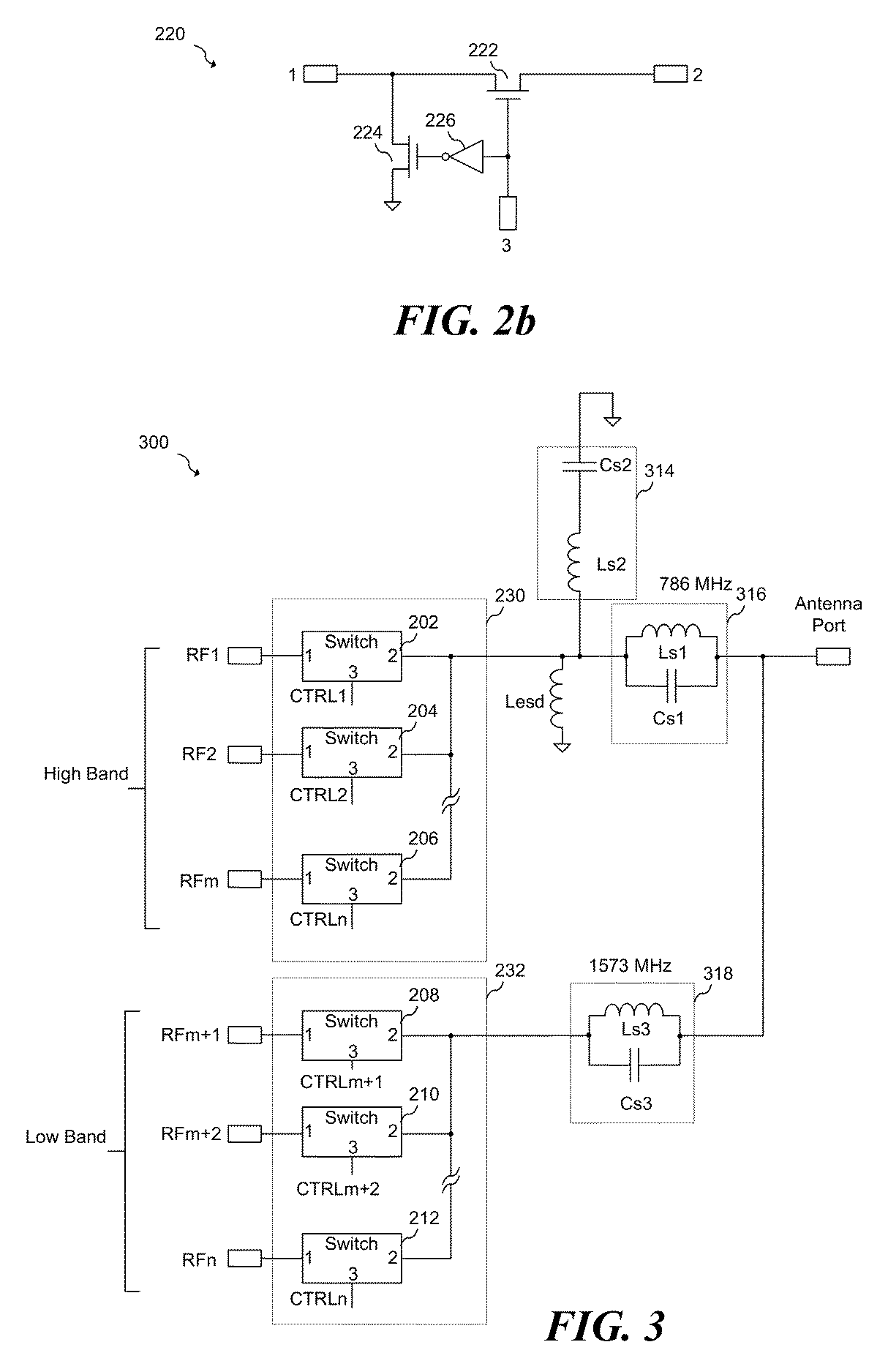
The invention is a filter network that includes two filters. The first filter has a pass band that includes a first frequency and a stop band that includes a distortion product of the first frequency. The second filter has a second frequency range that includes a second frequency and the stop band that includes the first frequency. The second filter is designed to have a higher frequency range than the first filter. This design helps to improve the performance of the filter network and minimize distortion during signal processing.

Problems solved by technology

The increasing number of frequency bands and standards in mobile communication systems increases the design complexity of mobile phones, as some mobile phones are now configured to operate using multiple standards across multiple frequency bands.
The introduction of more and more frequency bands within the mobile phone, however, may cause some issues with respect to jamming due to the creation of distortion products within circuitry of the mobile phone and within the antenna switch itself.
In mobile phone systems that have multiple antennas, distortion products created in the transmitter may leak into the receive path via one of the multiple antennas or via parasitic paths within the mobile phone itself.
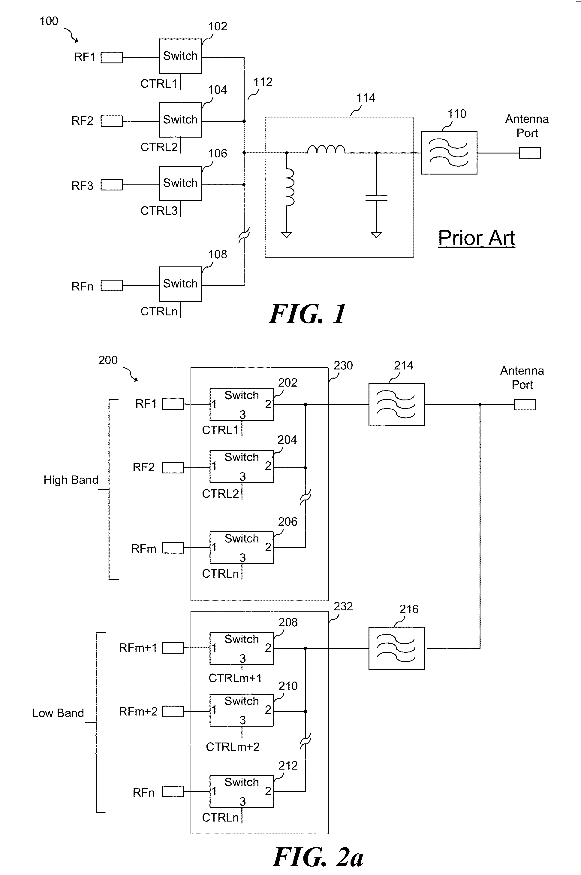
Some conventional mobile phone systems may address this issue by using a costly and bulky Hi-Q sharp band stop filter in series with the antenna port, because the GPS band is only about 150 MHz away from several cellular telephone bands.

Method used


Image

  • System and method for a radio frequency switch
  • System and method for a radio frequency switch
  • System and method for a radio frequency switch

Examples


Embodiment Construction

[0013]The making and using of the presently preferred embodiments are discussed in detail below. It should be appreciated, however, that the present invention provides many applicable inventive concepts that can be embodied in a wide variety of specific contexts. The specific embodiments discussed are merely illustrative of specific ways to make and use the invention, and do not limit the scope of the invention.

[0014]The present invention will be described with respect to preferred embodiments in a specific context: an antenna switch for a mobile phone system that operates in multiple bands. The invention may also be applied to other multiband systems that multiplex multiple signal paths to a common port.

[0015]Modern communication systems typically operate in many different frequency bands but use one main communication band depending on the type of service and geographic location. For example, a cellular phone may be configured to operate on a Code Division Multiple Access (CDMA) n...


PUM


Abstract

In accordance with an embodiment, a filter network is configured to be coupled to a first switch, a second switch, and an output port. The filter network includes a first filter coupled between the first switch and the output port, and the second filter coupled between the second switch and the output port. The first filter has a pass band having a first frequency range that includes a first frequency, and a stop band that includes a second frequency that is a distortion product of the first frequency. The second filter has a second frequency range that includes the second frequency and the stop band that includes the first frequency. The second frequency range is higher in frequency than the first frequency range.

Description

TECHNICAL FIELD[0001]This invention relates generally to radio frequency circuits and methods, and more particularly to a system and method for testing a radio frequency switch.BACKGROUND[0002]The increasing number of frequency bands and standards in mobile communication systems increases the design complexity of mobile phones, as some mobile phones are now configured to operate using multiple standards across multiple frequency bands. In addition, the mobile phone may also include a Global Positioning System (GPS) receiver. In many mobile phones, these multiple frequency bands and standards are implemented by using multiple radio frequency (RF) transmitters and receivers within multiple signal paths that may be coupled to a single antenna using an antenna switch. The introduction of more and more frequency bands within the mobile phone, however, may cause some issues with respect to jamming due to the creation of distortion products within circuitry of the mobile phone and within t...

Claims


Application Information

Patent Timeline
Patent Type & Authority Patents(United States)
IPC IPC(8): H01P1/10H04B1/00H03H7/46H04B1/44H03K17/693
CPCH03H7/465H04B1/0057H04B1/006H03K17/693H03H7/12H04B1/44
Inventor ILKOV, NIKOLAY
Owner INFINEON TECH AG
Learn More