Pressure control valve

a technology of pressure control valve and control pin, which is applied in the direction of valve details, engine components, operating means/releasing devices, etc., can solve the problem of large batch size of standardized control pins which are connected with accordingly optimized control parts, and achieve high temperature resistance, improve the effect of pressure vibration, and improve the effect of resistance to vibration of the medium

Active Publication Date: 2015-08-11
SVM SCHULTZ VERW
View PDF15 Cites 0 Cited by
  • Summary
  • Abstract
  • Description
  • Claims
  • Application Information

AI Technical Summary

Benefits of technology

[0013]It has been found that funnel-like, cone-like or tapered control parts have advantages, in particular with fast acting valves or fast controlling pressure control valves, as they have, besides the higher valve dynamic caused by the mass reduction, also a higher stability against pressure vibrations because of the cone-like, tapered or funnel-like design. Therefore, then the control part has on the back an accessible chamber, as it is also shown in the drawings (see reference number 22).
[0014]The tapered design has furthermore a design with good flow characteristics which diverts the medium to be controlled in a suitable way, following the surface of the tapering. By means of such a design even with high pressure a flow as laminar as possible can be kept, and flow losses are accordingly avoided.
[0020]Exactly the employment of new high temperature polymers with a melting point above 380° C. and a glass transition temperature of at least 150° C. makes it possible to provide economically high temperature resistant and light control parts, and thus also to handle reliably even more extreme application ranges of valves according to the invention, in particular pressure control valves.
[0021]In a preferred embodiment of the invention it is provided that the control pin is guided or supported on bearings in a core, and the core has a raised part facing the control part which immerses at least during an axial return movement of the control pin at least partly in the chamber. In this example, as it is also shown in the drawing (see FIGS. 2 and 3) an additional improvement against pressure vibrations has been observed, as this magnet geometric (in particular if in every operating position of the control part projects in the chamber) results in an additional absorption quality. The result of the immersion of the raised part in the chamber is that the volume of the medium within the chamber is separated (almost) completely from the other volume flow, and a corresponding medium wave penetrates no more here or only very damped. Therefore, the result is that the cone-like, funnel-like or tampered, if necessary also, thin-walled control part is “stiffened”. Thus a high stability against the vibrations of the medium is combined with a high valve dynamic because of the low weight of the control part.

Problems solved by technology

Therefore the batch size of the standardized control pins which are connected with accordingly optimized control parts remain therefore very large.

Method used


Image

  • Pressure control valve
  • Pressure control valve
  • Pressure control valve

Examples


Embodiment Construction

[0026]In the figures identical or corresponding elements each are indicated by the same reference numbers, and therefore are, as far as not advisable, not described anew.

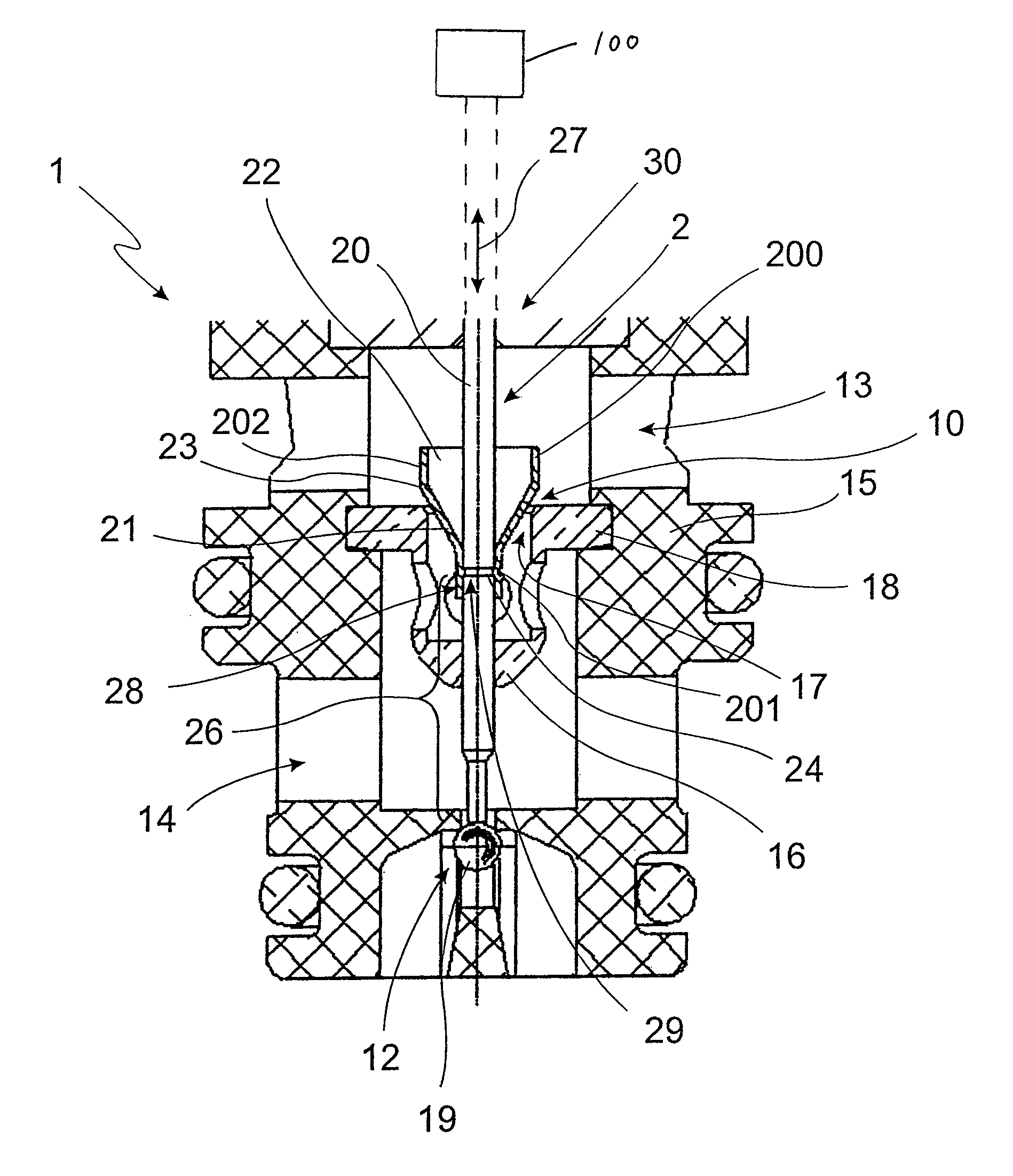
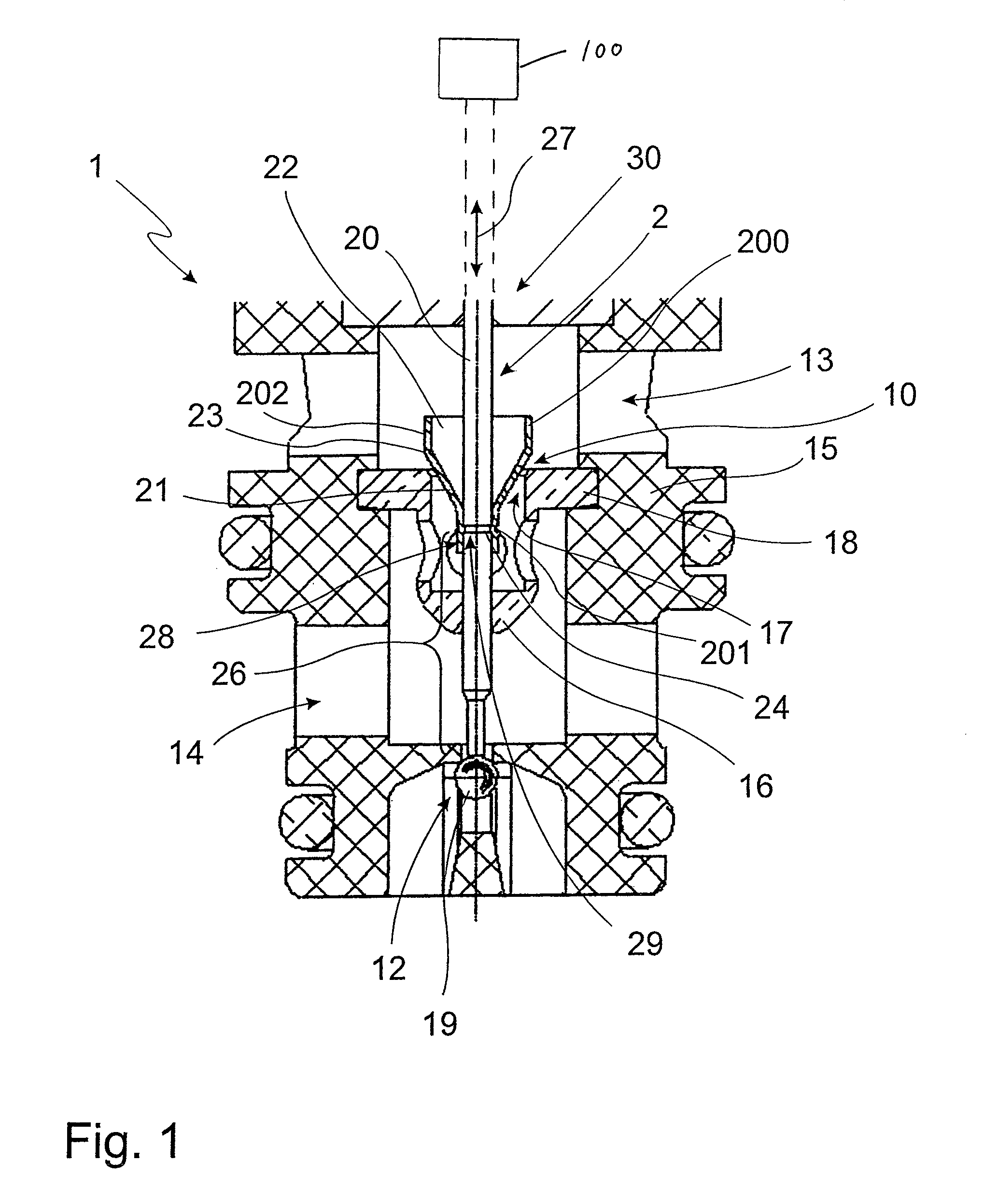
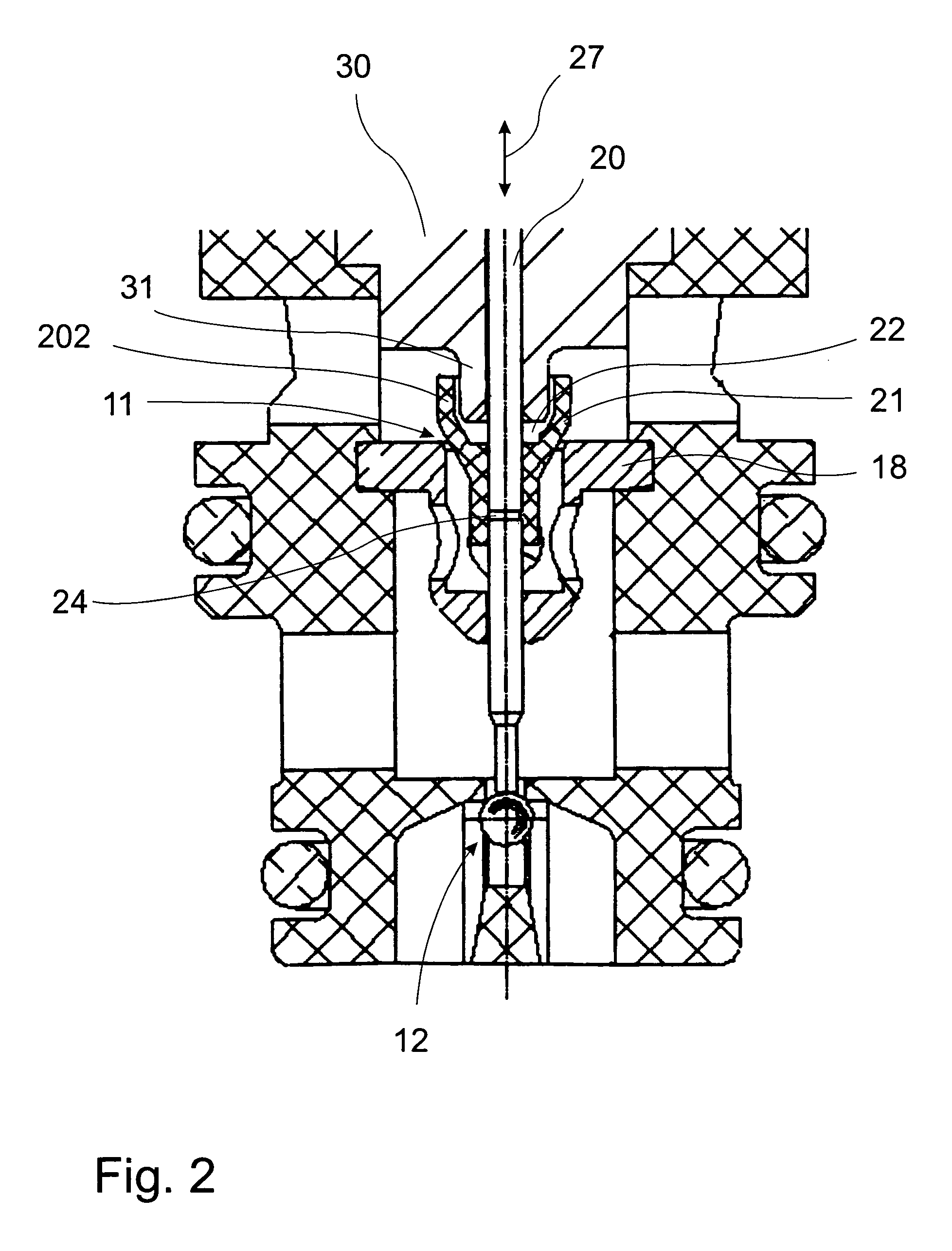
[0027]The valve 1 according to the invention is shown schematically in different modifications in the figures. The shown valve 1 is operated and controlled, respectively, by a solenoid 100 which is also part of the invention. Usually, a solenoid comprises an armature supported moving on bearings in the armature compartment acting on the control pin 20.The armature compartment is surrounded by a coil which can be electrified which generates a suitable magnetic field. According to the generated magnetic field the armature shifts axially so that also the control pin 20 is shifted axially.

[0028]The control pin 20 is here a part of the control element 2.

[0029]The solenoid would be linked above the valve 1, the control pin 20 is supported or guided in the core 30 in a suitable way.

[0030]The valve 1 shown in the drawing is...


PUM


Abstract

The invention refers to a valve which can be operated by a solenoid. The armature of the solenoid acts here on a control element. This is axially shifted here in such a way that the gap width of a gap provided in a valve bush changes. The control element consists of a control pin and a control part which manufactured separately from this and attached to the control pin, the control part interacting with the gap.

Description

[0001]This application has a priority of German no. 10 2009 035 902.8 filed Aug. 3, 2009, hereby incorporated by reference.[0002]The invention refers to a valve, in particular a pressure control valve, operated by a solenoid, wherein the armature of the solenoid acts on a control element of the valve and shifts it in such a way, in particular axially, that the gap width of a gap provided in or on a valve element, such as for example a valve plate or valve bush, changes, and the gap closes or opens, respectively.BACKGROUND OF THE INVENTION[0003]In pressure control valves operated by solenoids the power of the solenoid changes the gap between the control element and the valve seat arranged in the valve bush or the valve element, and thus the hydraulic pressure at the work connection is controlled. The gap is limited, on the one hand, by the valve seat and, on the other hand, by the terminating surface provided on the control element. As the position of the control element, and therefo...

Claims


Application Information

Patent Timeline
Patent Type & Authority Patents(United States)
IPC IPC(8): F16K31/06
CPCF16K31/0634
Inventor SCHERER, GEORG J.MANG, HELMUT J.
Owner SVM SCHULTZ VERW
Why Eureka
Try Eureka