
Prestressed shaft and hub connection having a perfect cone shape

a cone-shaped, pre-stressed technology, applied in the direction of rod connections, couplings, manufacturing tools, etc., can solve the problems of reduced life of the shaft/hub connection and consequently the entire system, high stress in the components, and undesired noise and vibration, so as to avoid all the disadvantages, avoid the effect of playing and less energy expenditur

Active Publication Date: 2011-12-13
NEAPCO INTPROP HLDG LLC
View PDF16 Cites 8 Cited by
  • Summary
  • Abstract
  • Description
  • Claims
  • Application Information

AI Technical Summary

Benefits of technology

[0015]The invention is based on the knowledge that a reduction of the play between shaft and hub can only diminish or neutralize high stresses in the component, fatigue, true running, and vibrations and can only lead to the objective, if, on the one hand, a self-locking can occur between the shaft and the hub and if, on the other hand, the connection remains permanently prestressed in axial direction.
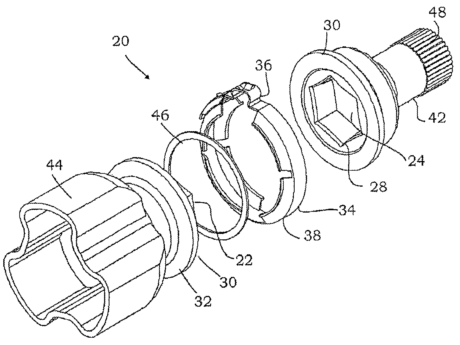
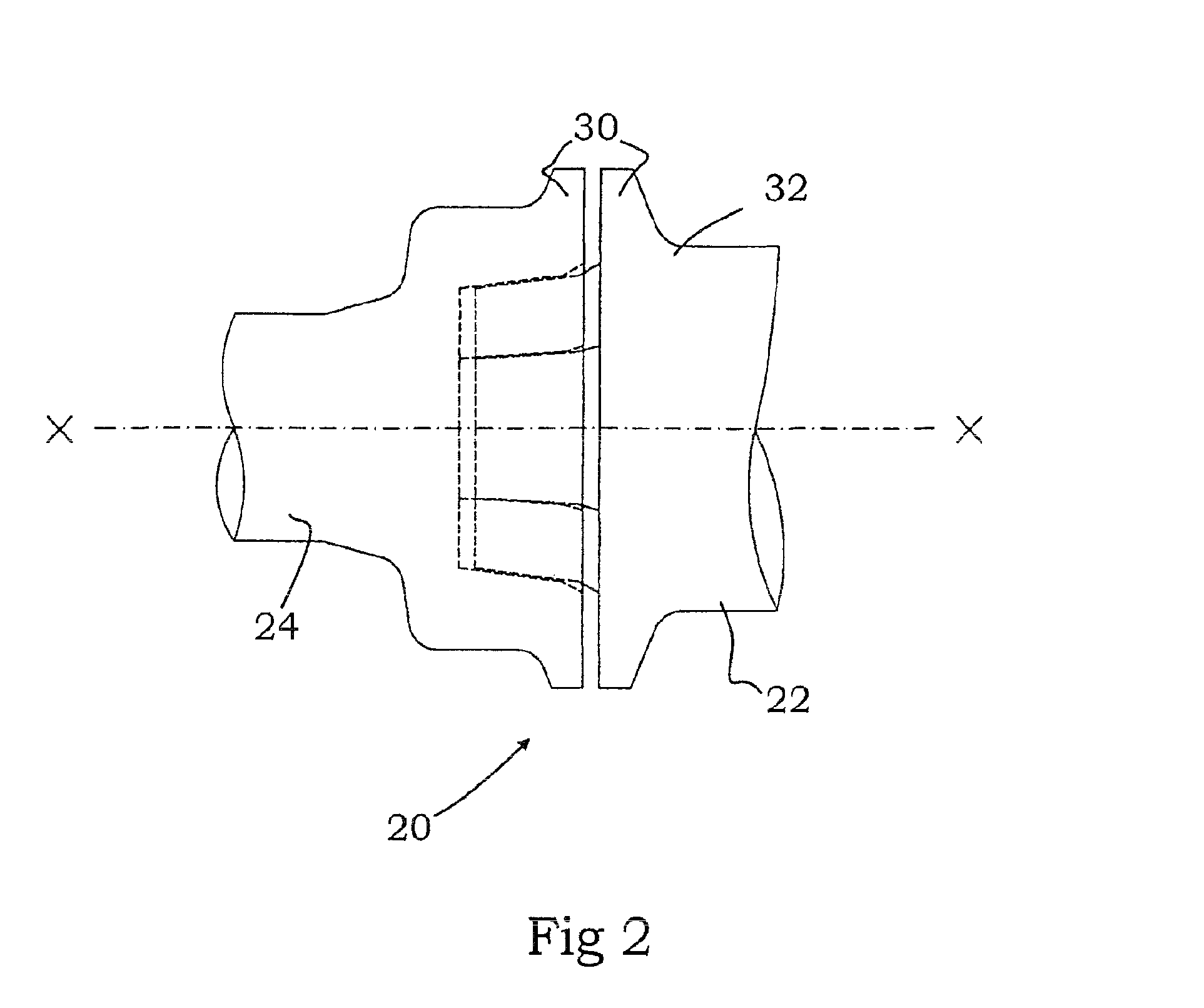
[0017]The shaft / hub connection according to the invention can furthermore be produced and assembled in a very simple manner. In a particularly advantageous embodiment version, provision is made for a prestressing ring as connecting means, which stresses the shaft and the hub in axial direction. For this purpose, the shaft and the hub each have a circumferential ramp-shaped elevation, which is disposed relatively close to each other when the shaft and the hub are joined. During the joining, the prestressing ring is placed above these ramps and is contracted. The contracting leads to the reduction of the diameter of the prestressing ring, thereby causing the lateral flanks of the prestressing ring to come into contact with the ramps and pressing them on top of each other. Once sufficient prestress has been applied, the prestressing ring is fixed and remains in its position. The prestressing ring is made from a resistant material and is advantageously balanced.
[0021]With only very little expenditure of energy, the shaft and the hub can be joined in such a manner that they remain in a relatively solid connection due to the self-locking. The shape of a perfect cone furthermore causes the shaft and the hub to be compulsorily centered to each other in response to the joining. The connection is thus completely free of play and avoids all of the disadvantages associated with an undesired play. The transmission of forces takes place across a relatively large surface, thus avoiding load peaks.
[0023]Optionally, provision can be made for an additional sealing element between the shaft and the hub. To avoid corrosion, a sealing of the polygon section is sensible under sustained loading. Such a sealing can also be sensible if the shaft / hub is used in all-terrain vehicles or in construction machinery.

Problems solved by technology

This causes high stresses in the components, which must be compensated for or reduced by an appropriately long connection.
The enlargement of radial run-out also leads to undesired noises and vibrations.
Finally, these effects lead to a reduction in the lifetime of the shaft / hub connection and consequently that of the entire system.
The disadvantage of this embodiment is the need for additional components, which is associated with higher space requirements and costs.
Due to the additional components, this embodiment is also associated with correspondingly higher costs having a relatively high space requirement.
An additional time-intensive and thus cost-intensive operating step is required for the assembly of the clamping set.
It is disadvantageous that the production of the components is possible only with special and very expensive machines.
The creation of a twisted inner contour, in particular, is difficult.
A joining by hand is thus not possible.
However, these lead to an eccentricity of the shaft and therefore to point contacts or relatively small contact surfaces between shaft and hub.
However, this is oftentimes accepted because, as already described above, an increase or an even distribution of the contact surfaces within the entraining longitudinal section only seems to be possible with additional components and with considerably effort.

Method used


Image

  • Prestressed shaft and hub connection having a perfect cone shape
  • Prestressed shaft and hub connection having a perfect cone shape
  • Prestressed shaft and hub connection having a perfect cone shape

Examples


Embodiment Construction

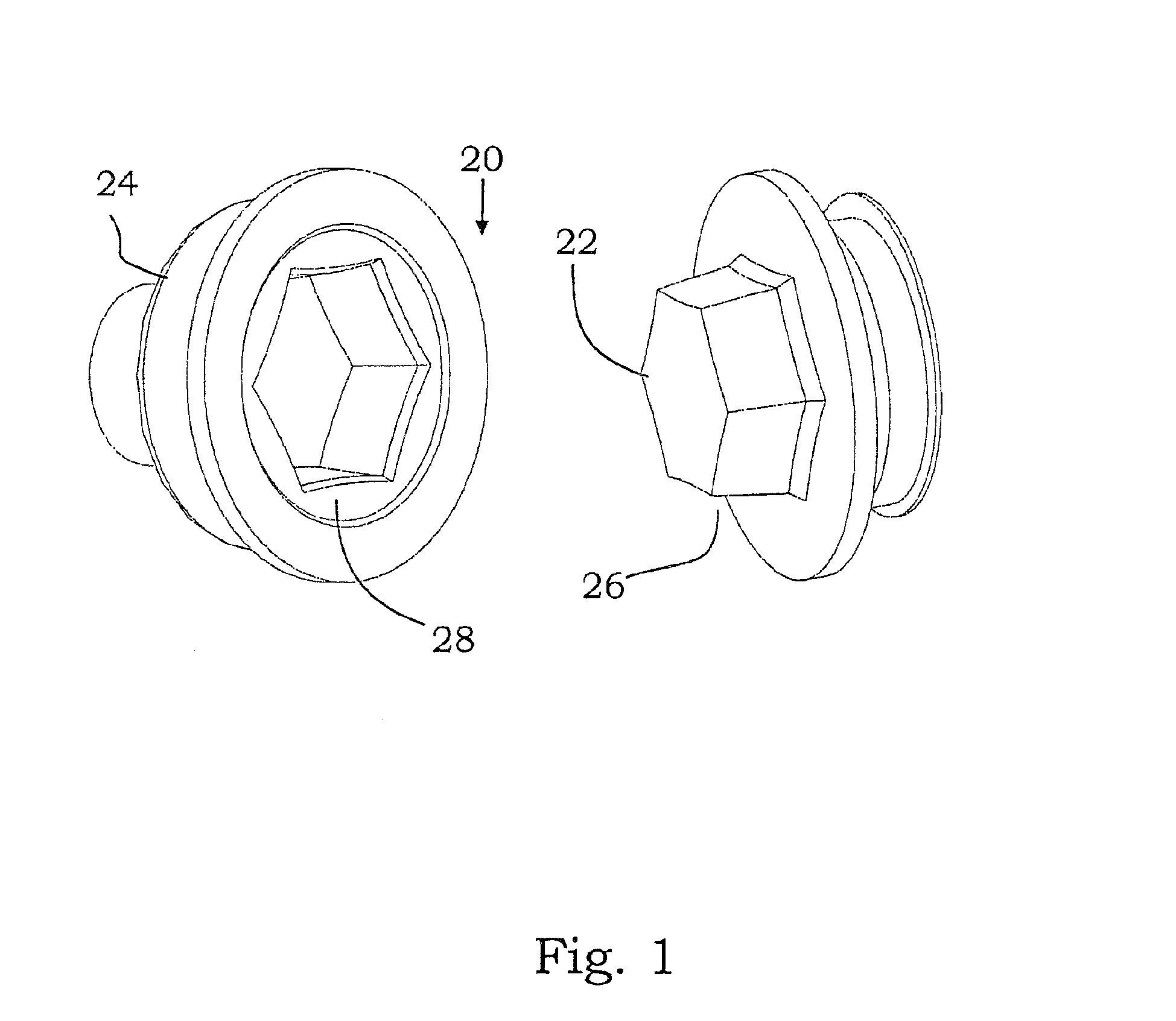
[0033]FIGS. 1 to 6 clarify the function and the configuration of a shaft / hub connection 20 as claimed in the invention. The shaft / hub connection 20 has a shaft 22 and a hub 24, wherein the shaft 22 with its outer contour 26 rests against an inner contour 28 of the hub 24. This area, in which a torque can be transmitted, will be referred to hereinbelow as entraining longitudinal section.

[0034]The shaft 22 and the hub 24 are disposed so as to be concentric to a longitudinal axis X-X and rotate around said longitudinal axis during the torque transmission. The shaft 22 has trochoidal bulges and the hub 24 has trochoidal indentations relative to its cross section. However, all other out-of-round cross sectional shapes are also fundamentally suitable for implementing the invention. A six-sided polygon in particular has proven to be particularly suitable for transmitting the torque. It has likewise been shown for a six-sided polygon that a relative eccentricity E of between 2% and 10%, pre...


PUM


Abstract

The invention relates to a shaft and hub connection (20) for transmitting torque, a common longitudinal axis (X-X) comprising the following components: a shaft (22) which rotates about the longitudinal axis (X-X) and comprises an entraining longitudinal section having an untrue outer contour (26), and a hub (24) that is coaxial to the shaft (22) and encloses the shaft (22) with its internal contour (28) at least in the area of the entraining longitudinal section. The invention is characterized in that the outer contour (26) of the entraining longitudinal section of the shaft (22) and the inner contour (28) of the hub (24) have the shape of a perfect cone to such a degree that, when the shaft (22) and the hub (24) are assembled, they automatically self-lock, thereby holding the shaft and hub connection (20) together. The connection also comprises connecting means which prestress the shaft (22) and the hub (24), when assembled, in the direction of the longitudinal axis (X-X).

Description

[0001]This application hereby claims the benefit of the commonly assigned German Patent No. 10 2005 031 832.0 (filed Jul. 6, 2005, in the German Patent Office) and the commonly assigned International Patent Application No. PCT / EP2006 / 06621 (filed Jul. 6, 2006, in the European Patent Office), both of which are hereby incorporated by reference in their entirety.FIELD OF THE INVENTION[0002]The present invention relates to a shaft / hub connection for transmitting torque, comprising the components having a common longitudinal axis:[0003]a) a shaft, which can be rotated about the longitudinal axis comprising an entraining longitudinal section having an untrue outer contour,[0004]b) a hub, which is coaxial to the shaft and which encloses the shaft with its inner contour at least in the area of the entraining longitudinal section.BACKGROUND[0005]In machine construction, such shaft / hub connections are used in many ways for transmitting torques between the shaft and the hub. In addition to man...

Claims


Application Information

Patent Timeline
IPC IPC(8): F16B7/02
CPCF16D1/092F16D2001/102Y10T403/648Y10T403/63Y10T403/7098Y10T403/551Y10T403/66F16B2200/509F16D3/2055
Inventor KROENER, THILO
Owner NEAPCO INTPROP HLDG LLC
Learn More