Household appliance having a height-adjusting device for an appliance pedestal

Active Publication Date: 2012-07-17
BSH BOSCH & SIEMENS HAUSGERAETE GMBH
View PDF11 Cites 24 Cited by
  • Summary
  • Abstract
  • Description
  • Claims
  • Application Information

AI Technical Summary

Benefits of technology

[0005]The object of the invention is to provide a household appliance with a

Problems solved by technology

The design of the end stop on the threaded shank is

Method used


Image

  • Household appliance having a height-adjusting device for an appliance pedestal
  • Household appliance having a height-adjusting device for an appliance pedestal
  • Household appliance having a height-adjusting device for an appliance pedestal

Examples


Embodiment Construction

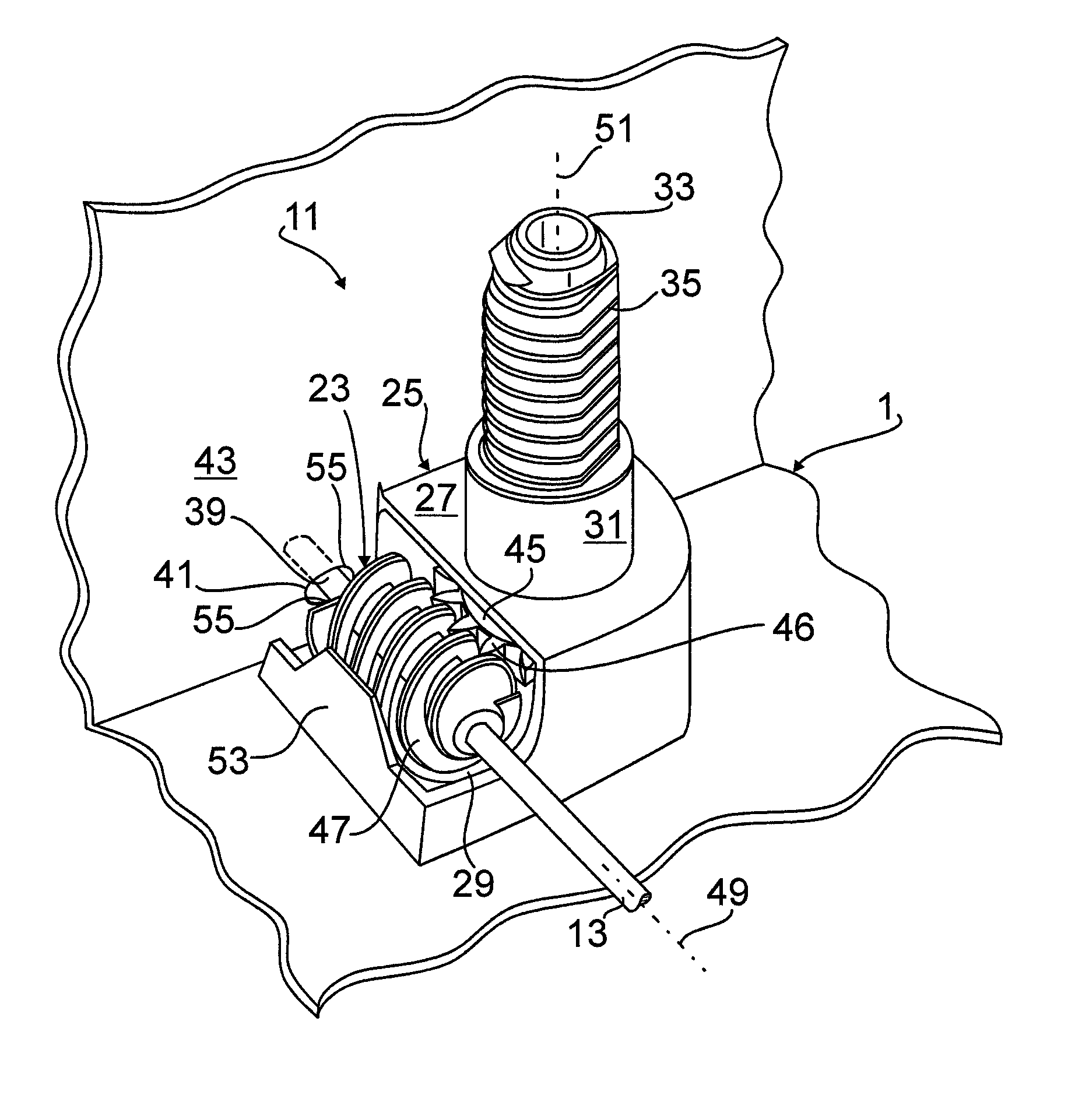
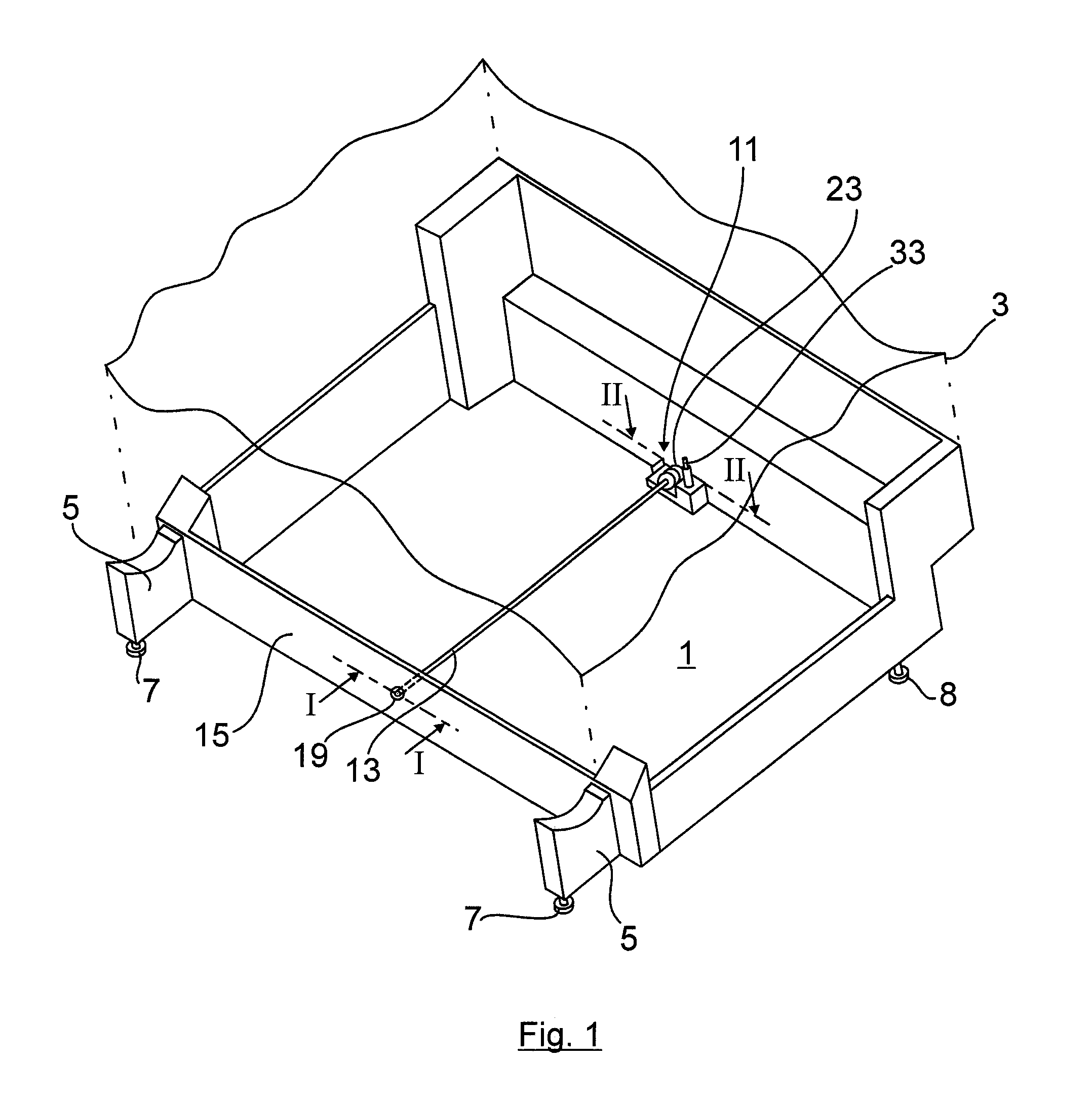
[0027]FIG. 1 shows a mounting base 1, manufactured as a plastic injection-molded component, of a household appliance 3 which is merely indicated. The appliance units provided for in the household appliance 3 are omitted for reasons of clarity. The mounting base 1 has two lateral support arms 5 projecting forward and downward on the front, with front appliance pedestals 7. In addition, in the rear area of the mounting base 1 a height-adjustable appliance pedestal 9 is provided approximately centrally, as is shown in FIG. 3. In contrast, in FIG. 1 merely the height-adjusting device 11 of the central appliance pedestal 9 is visible. The height-adjusting device 11 is described later.

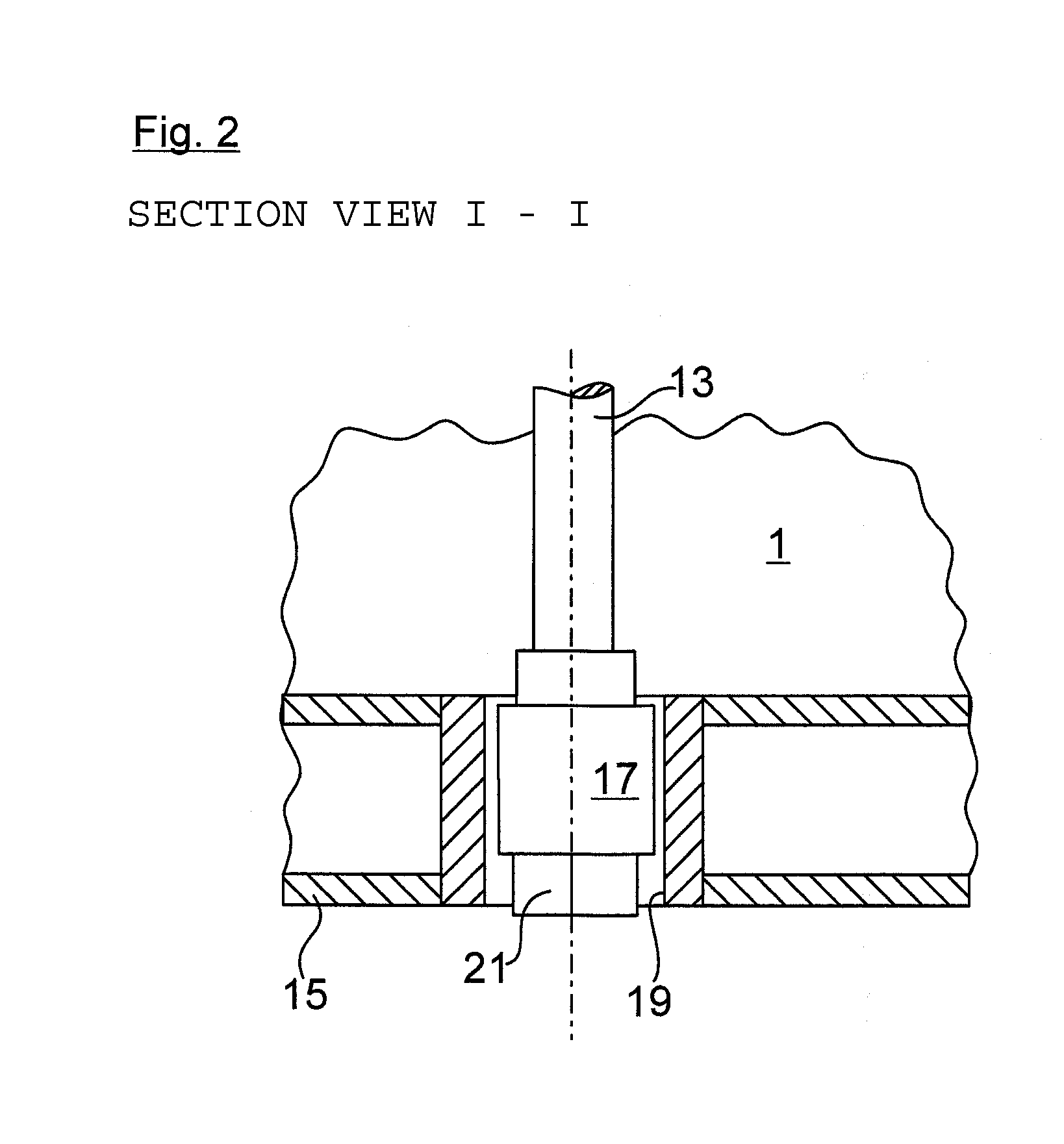
[0028]As further emerges from FIG. 1, the height-adjusting device 11 is associated with an adjusting rod 13 which extends as a drive shaft as far as the front 15 of the mounting base 1. The front end of the adjusting rod 13 has an adjusting bush 17 according to FIG. 2 which is rotatably mounted in a bearing ...


PUM


Abstract

A household appliance, particularly a dishwasher or washing machine, having a height-adjusting device for an appliance pedestal. The height-adjusting device may include at least one drive gear engaged with a transmission drive converting the rotary motion of the drive gear into a lift motion of the appliance pedestal. In an exemplary embodiment of the invention, the drive gear includes a torque-limiting element operable to enable a deflecting motion of the drive gear from an operating position when a limit torque is exceeded, and which releases the engagement between the drive gear and the transmission drive.

Description

BACKGROUND OF THE INVENTION[0001]The invention relates to a household appliance having a height-adjusting device for an appliance pedestal.[0002]Built-in kitchen appliances which are already built in can be brought into the right mounting position by means of height-adjustable appliance pedestals, the height of the inaccessible rear appliance pedestals being adjusted by means of an adjusting rod which can be actuated on the front of the appliance.[0003]A generic height-adjusting device for an appliance pedestal of a household appliance is known from WO 2004 / 107914 A1, in which a drive gear engages with a transmission gear which converts the rotational motion of the drive gear into a lift motion of the appliance pedestal.[0004]Specifically, in WO 2004 / 107914 A1 the drive gear is a drive worm which rests in a rotatably fixed manner on an adjusting rod and is mounted in a fixed position and rotatably in a mounting housing at the rear of the appliance. The drive worm engages with a worm...

Claims


Application Information

Patent Timeline
IPC IPC(8): F16M11/24
CPCA47B91/028A47L15/4253D06F39/125A47B2095/004
Inventor FETZER, GERHARDSEE.BETA.LE, MANFRED
Owner BSH BOSCH & SIEMENS HAUSGERAETE GMBH
Why Eureka
Try Eureka