
Parallel application checkpoint image compression

a checkpoint image and parallel processing technology, applied in the field of data processing, can solve the problems of limiting affecting the performance of the computer system, so as to achieve the effect of reducing the potential speed of serial processors and reducing the complexity of the devi

Inactive Publication Date: 2015-08-18
INT BUSINESS MASCH CORP
View PDF19 Cites 1 Cited by
  • Summary
  • Abstract
  • Description
  • Claims
  • Application Information

AI Technical Summary

Problems solved by technology

Since that time, computer systems have evolved into extremely complicated devices.
It is far more difficult to construct a computer with a single fast processor than one with many slow processors with the same throughput.
There are also certain theoretical limits to the potential speed of serial processors.
After that point adding more processors does not yield any more throughput but only increases the overhead and cost.
Shared memory processing needs additional locking for the data and imposes the overhead of additional processor and bus cycles and also serializes some portion of the algorithm.
Message passing processing uses high-speed data communications networks and message buffers, but this communication adds transfer overhead on the data communications networks as well as additional memory need for message buffers and latency in the data communications among nodes.
Although a tree network typically is inefficient in point to point communication, a tree network does provide high bandwidth and low latency for certain collective operations, message passing operations where all compute nodes participate simultaneously, such as, for example, an allgather operation.
In instances in which a parallel application includes hundreds or thousands of tasks, the number of images created may be quite large and storage for such images may be limited.
As such, storing many separate images, each of which includes an amount of data that is identical to all of the other images inefficiently utilizes storage.

Method used


Image

  • Parallel application checkpoint image compression
  • Parallel application checkpoint image compression
  • Parallel application checkpoint image compression

Examples


Embodiment Construction

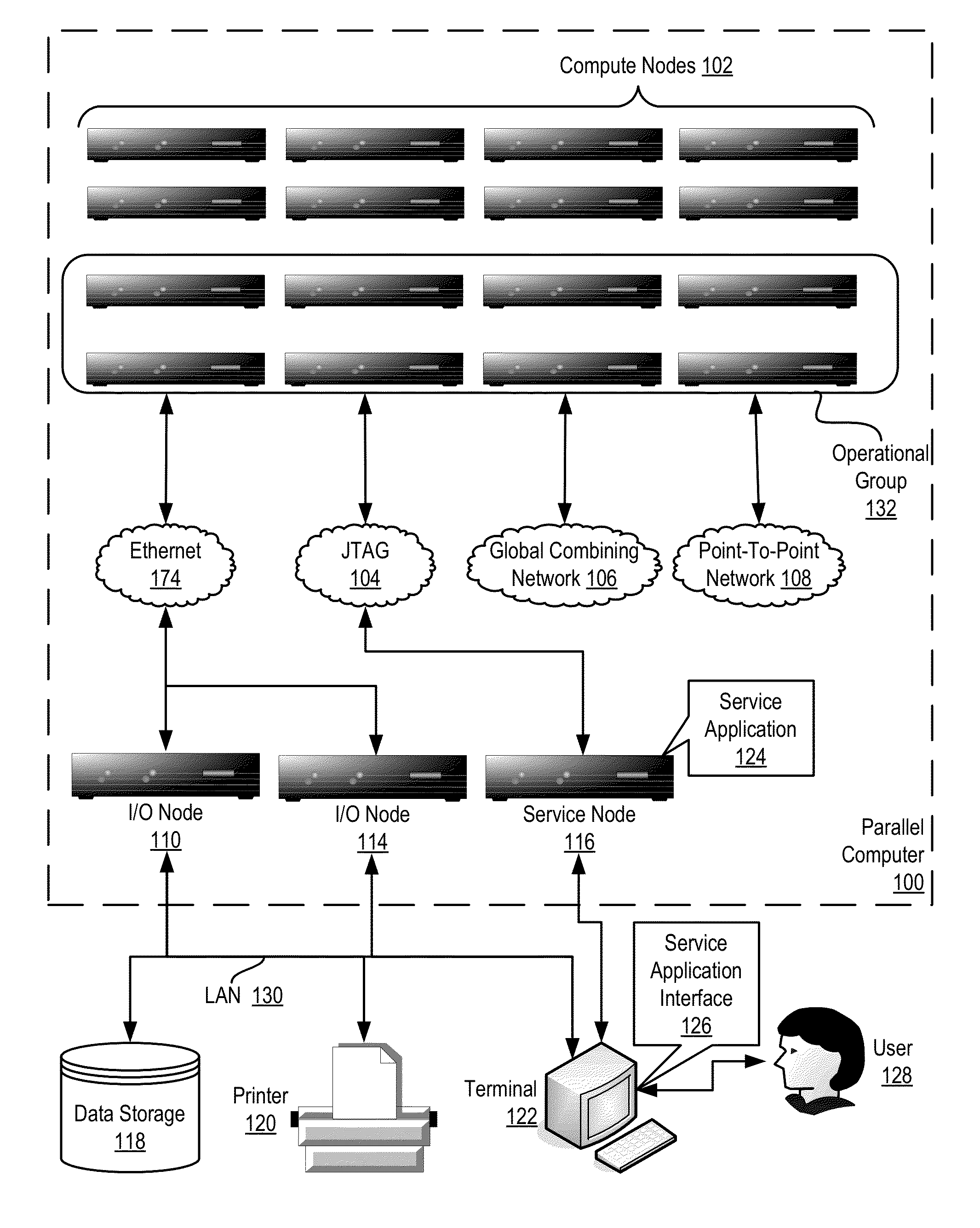
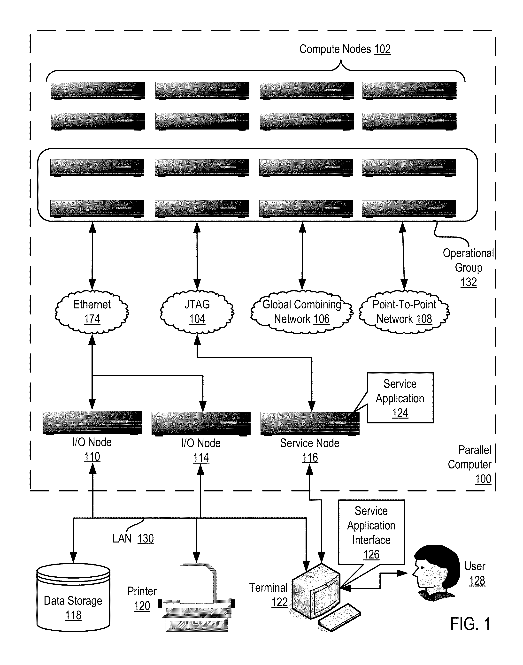
[0025]Exemplary methods, apparatus, and products for parallel application checkpoint image compression in a parallel computer in accordance with the present invention are described with reference to the accompanying drawings, beginning with FIG. 1. FIG. 1 illustrates an exemplary system for parallel application checkpoint image compression according to embodiments of the present invention. The system of FIG. 1 includes a parallel computer (100), non-volatile memory for the computer in the form of a data storage device (118), an output device for the computer in the form of a printer (120), and an input / output device for the computer in the form of a computer terminal (122).

[0026]The parallel computer (100) in the example of FIG. 1 includes a plurality of compute nodes (102). The compute nodes (102) are coupled for data communications by several independent data communications networks including a high speed Ethernet network (174), a Joint Test Action Group (‘JTAG’) network (104), a ...


PUM


Abstract

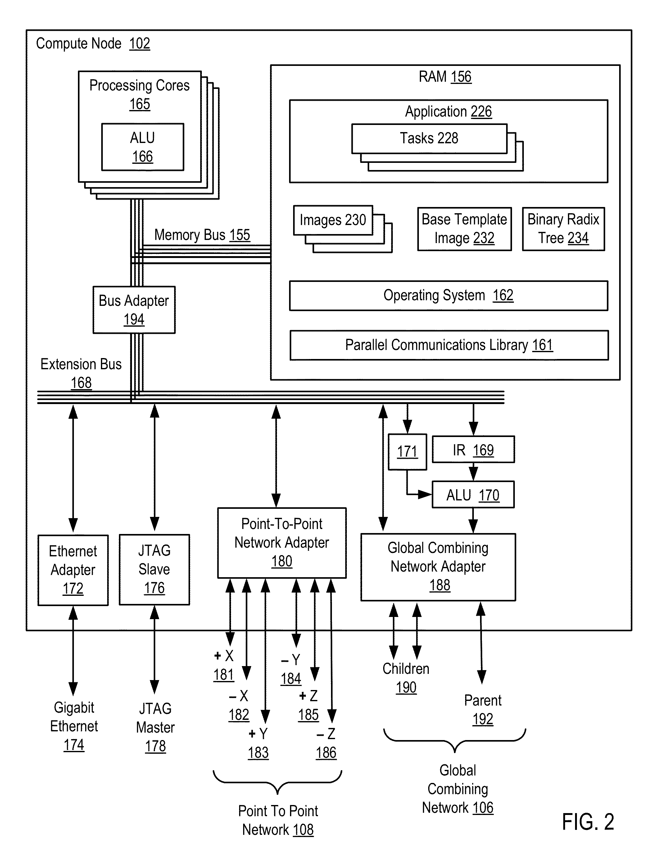
Parallel application checkpoint image compression may be carried out in a parallel computer. The parallel computer may include a plurality of compute nodes, where each node is configured to execute one or more parallel tasks of the parallel application. The parallel tasks may be organized into an operational group for collective communications. In such a parallel computer, checkpoint image compression may include: generating, by each task of the parallel application, an image for checkpointing the parallel application; selecting, by an image management task, one of the images as a base template image; constructing, by the image management task, a binary radix tree, including storing differences between each task's image and the base template image in the binary radix tree; and storing, by the image management task as a checkpoint for the parallel application, the binary radix tree and the base template image, without storing every task's image.

Description

BACKGROUND OF THE INVENTION[0001]1. Field of the Invention[0002]The field of the invention is data processing, or, more specifically, methods, apparatus, and products for parallel application checkpoint image compression.[0003]2. Description of Related Art[0004]The development of the EDVAC computer system of 1948 is often cited as the beginning of the computer era. Since that time, computer systems have evolved into extremely complicated devices. Today's computers are much more sophisticated than early systems such as the EDVAC. Computer systems typically include a combination of hardware and software components, application programs, operating systems, processors, buses, memory, input / output devices, and so on. As advances in semiconductor processing and computer architecture push the performance of the computer higher and higher, more sophisticated computer software has evolved to take advantage of the higher performance of the hardware, resulting in computer systems today that ar...

Claims


Application Information

Patent Timeline
Patent Type & Authority Patents(United States)
IPC IPC(8): G06F17/30G06K9/62G06F11/34
CPCG06F11/3404G06F17/3028G06K9/6282G06K9/6202G06F11/00G06F11/14H04N19/436G06F11/1438G06F16/51G06F18/24323
Inventor ARCHER, CHARLES J.LYNAM, BENJAMIN E.
Owner INT BUSINESS MASCH CORP
Learn More