Noise mitigating microphone attachment

a microphone and noise-mitigating technology, which is applied in the direction of transducer casings/cabinets/supports, electrical transducers, frequency/directions obtaining arrangements, etc., can solve the problems of reducing affecting the quality of sound recording, so as to achieve the effect of reducing nois

Active Publication Date: 2015-08-25
KAOTICA
View PDF90 Cites 16 Cited by
  • Summary
  • Abstract
  • Description
  • Claims
  • Application Information

AI Technical Summary

Benefits of technology

[0008]According to one embodiment, an attachment for a microphone comprises a foam structure. A first cavity extends from a first opening at a surface of the foam structure and into the foam structure. The first cavity is configured to seal a mobile device at least partly in the cavity. The attachment also has a second cavity extending from a second opening at the surface of the foam structure and into the foam structure. The second opening receives sound from a sound source. The first cavity is fluidly connected to the second cavity within the foam structure so that a junction is formed between the first cavity, the second cavity, and the sealing of the mobile device. The junction works to shield the sound receiving elements of a microphone coupled to the mobile device from sound other than the sound received through the second opening.

Problems solved by technology

Noise entering the space from the exterior, such as traffic noise, may also contribute to ambient noise levels.
Ambient noise that is picked up by a microphone during the recording of a performance can detract from the quality of the recording.
Such measures can make treating a room for sound recording a costly and complicated endeavor.
Moreover, when sound recording occurs within a home, it may be undesirable to alter the appearance of the room as needed to accommodate sound recording.
The booth may be costly, require a complicated assembly process and, when assembled, can occupy a substantial amount of space within a room.

Method used


Image

  • Noise mitigating microphone attachment
  • Noise mitigating microphone attachment
  • Noise mitigating microphone attachment

Examples


Embodiment Construction

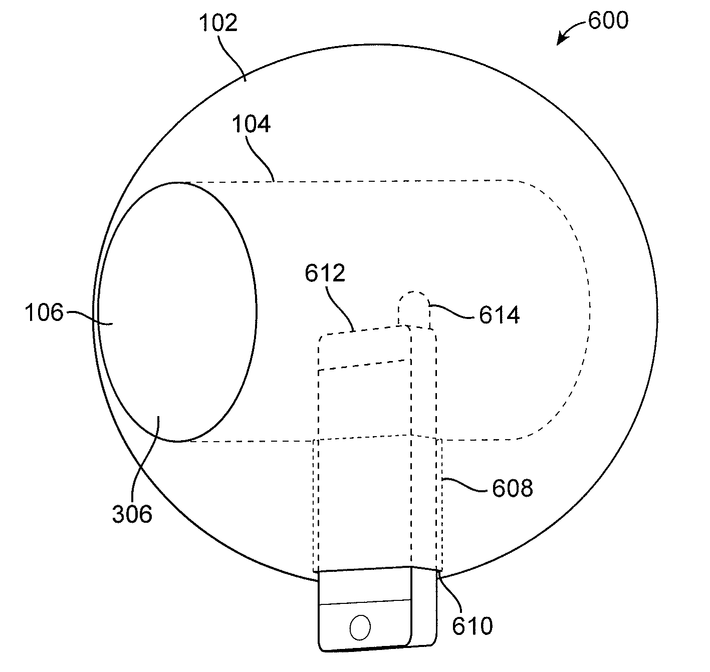
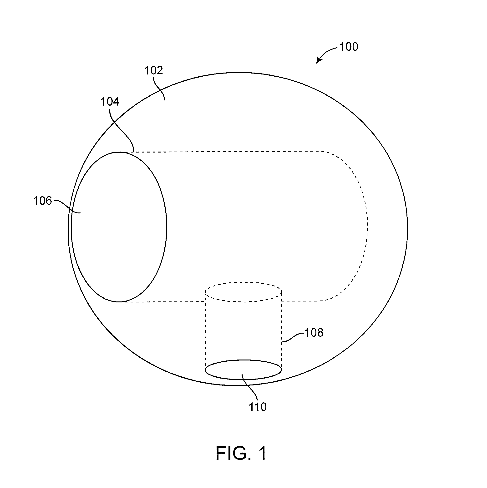
[0017]Embodiments of the present invention relate to mitigating noise during a capture of sound recording with a noise mitigating microphone attachment. Noise can refer to any unwanted sound, i.e., sound that is not desirable to have a microphone detect during a recording. For example, it may be desirable that noise such as ambient noise and reflections of sound waves originating from a performance sound source is mitigated. The noise mitigating microphone attachment can reduce the amount of noise that a microphone will pick up during a sound recording.

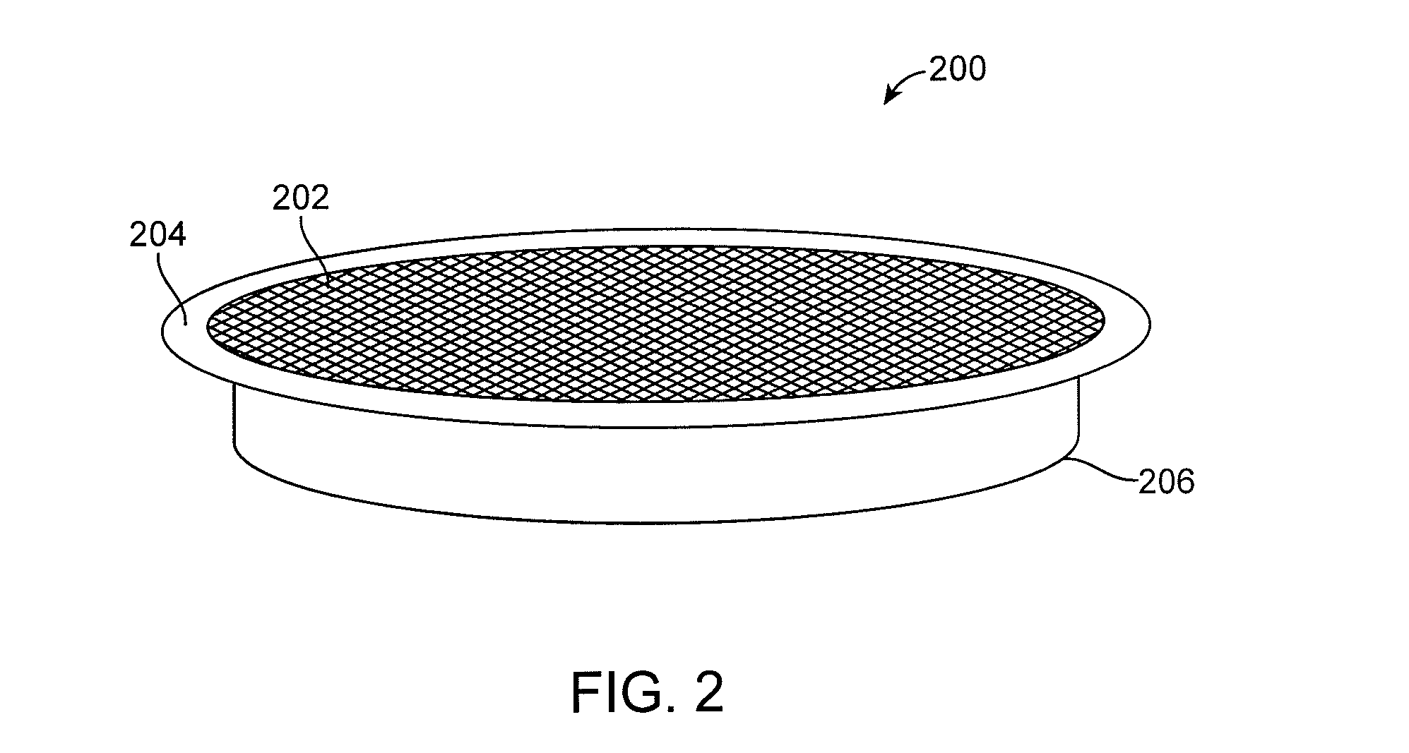
[0018]The noise mitigating microphone attachment is typically a foam structure, such as a foam sphere. The noise mitigating microphone attachment can have two openings. A microphone can be inserted through one of the openings into a first hollow cavity (“microphone cavity”) within the foam structure. The second opening may be placed proximate to a sound source, such as a vocalist or an instrument. Sound radiating from the sound source...


PUM


Abstract

Methods, systems and apparatus are described for mitigating noise during sound recording. A noise mitigating microphone attachment comprises a foam structure. A first cavity extending from a first opening at a surface of the foam structure and into the foam structure. A microphone is inserted into the first cavity with sound receiving elements of the microphone fully installed in the structure. A second cavity extending from a second opening at the surface of the foam structure and into the foam structure is configured to receive sound from a sound source. The first cavity is fluidly connected to the second cavity within the foam structure so that a junction is formed between the first cavity and the second cavity. The junction, the sound cavity, and the sealing of the microphone work to shield the sound receiving elements of the microphone from sound other than received through the second opening.

Description

CROSS-REFERENCES TO RELATED APPLICATIONS[0001]The present application is a continuation-in-part application of and claims priority to U.S. patent application Ser. No. 13 / 604,589, filed Sep. 5, 2012, the entire contents of which are herein incorporated by reference for all purposes.BACKGROUND[0002]When a microphone is used to record a performance in a space that has not been treated for sound recording, sound that is unrelated to the performance may be picked up by the microphone. Ambient noise or “room tone” can include noise originating within the space, such as the sound of an air conditioner or computer fan in the room. Noise entering the space from the exterior, such as traffic noise, may also contribute to ambient noise levels. Ambient noise that is picked up by a microphone during the recording of a performance can detract from the quality of the recording.[0003]Additionally, performance sound can be reflected from interior surfaces of the space, such as walls, ceiling, floor,...

Claims


Application Information

Patent Timeline
Patent Type & Authority Patents(United States)
IPC IPC(8): H04R9/08H04R1/08H04R1/34H04R1/02
CPCH04R1/02H04R1/083H04R1/086H04R1/342H04R1/025
Inventor ZUKOWSKI, KONRAD
Owner KAOTICA
Why Eureka
Try Eureka