Methods and apparatus for user selectable digital mirror

a digital mirror and user-selectable technology, applied in lighting and heating equipment, instruments, transportation and packaging, etc., can solve the problems of inability to easily view objects at different angles, affecting the fixed state of the optical mirror, and affecting the user's experien

Active Publication Date: 2015-09-01
VISIONQUEST IMAGING
View PDF53 Cites 77 Cited by
  • Summary
  • Abstract
  • Description
  • Claims
  • Application Information

AI Technical Summary

Problems solved by technology

While optical mirrors are extremely useful in providing information that cannot be viewed directly, aberrations may occur in the medium used to reflect the information.
Users may also be hampered with the fixed state of the optical mirror and unable to easily view objects at different angles.
Proper lighting of an object that is to be viewed in an optical mirror may be challenging.
The ability to light an object such that its mirrored image provides a view of a desired feature may be hampered by shadows or require multiple

Method used


Image

  • Methods and apparatus for user selectable digital mirror
  • Methods and apparatus for user selectable digital mirror
  • Methods and apparatus for user selectable digital mirror

Examples


Embodiment Construction

[0032]In the following detailed description of the embodiments of the invention, numerous specific details are set forth in order to provide a thorough understanding of the aspects of the invention. However, it will be obvious to one skilled in the art that the embodiments of the invention may be practiced without these specific details. In other instances well known methods, procedures, components, and circuits have not been described in detail so as not to unnecessarily obscure aspects of the invention.

[0033]Reference in the specification to “one embodiment” or “an embodiment” means that a particular aspect, feature, structure, or characteristic is described in connection with at least one embodiment of the invention. The appearances of the phrase “in one embodiment” in various places in the specification do not necessarily all refer to the same embodiment. Moreover, aspects, features, structures, or characteristics described with regard to one embodiment of the invention may be s...


PUM


Abstract

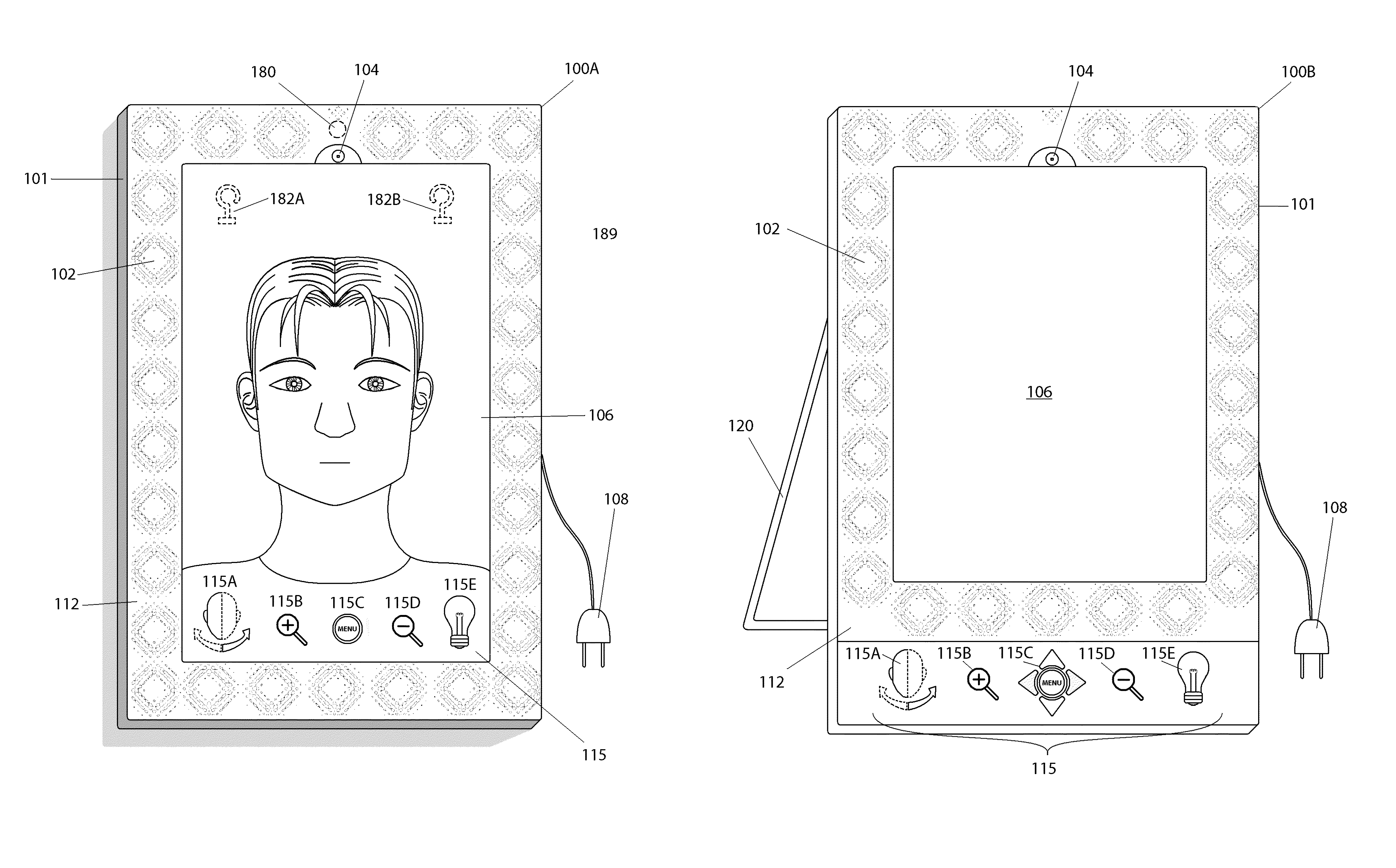
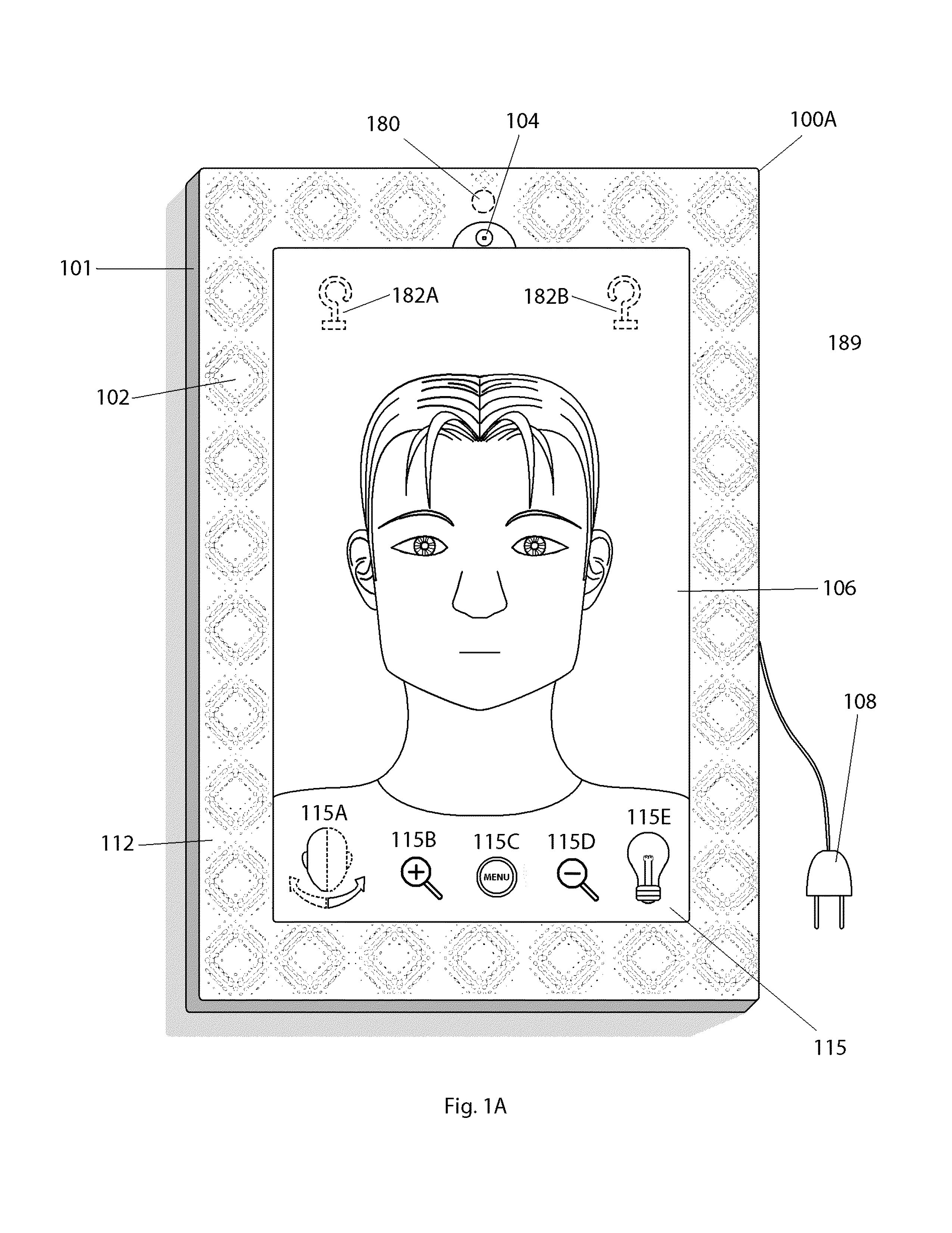
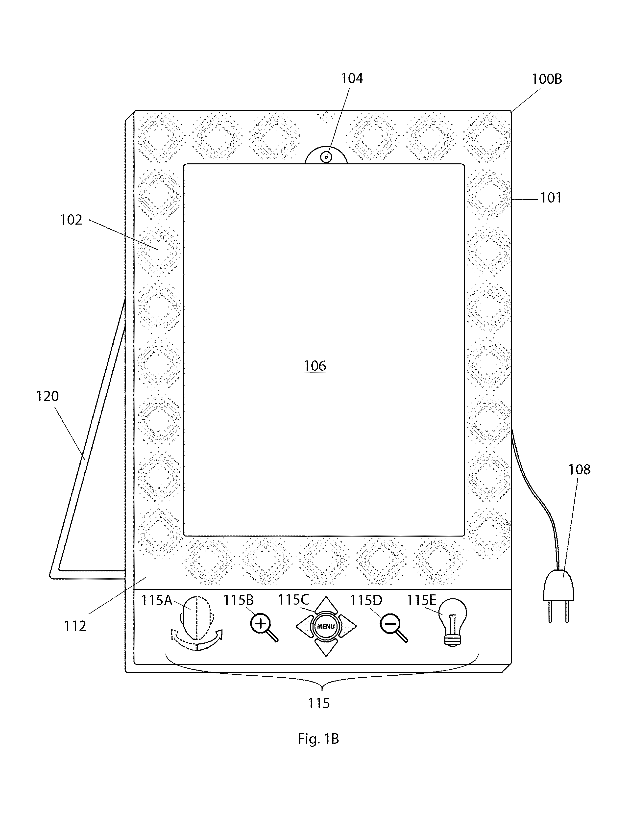
In one embodiment of the invention, a digital mirror is disclosed including an enclosure; a display device mounted in the enclosure to display images at a front side of the enclosure; an image capture device mounted in the enclosure adjacent the display device to reduce parallax error; lights mounted in the enclosure adjacent the display device; and a light diffuser mounted to the enclosure around the display device over the one or more lights. The one or more lights provide lighting in front of the display device and the image capture device captures images in the field of view in the front. The light diffuser diffuses and softens the light emitted by the one or more lights. Alternatively, the image capture device may be mounted on an articulated arm that may be used to capture and display various angles in the filed of view of the digital mirror.

Description

CROSS-REFERENCE TO RELATED APPLICATIONS[0001]This non-provisional United States (U.S.) patent application claims the benefit of U.S. Provisional Patent Application No. 61 / 338,105 filed on Feb. 16, 2010 by John W. Rowles, et al., entitled DIGITAL MIRROR, which is incorporated herein by reference. This non-provisional United States (U.S.) patent application also claims the benefit of U.S. Provisional Patent Application No. 61 / 338,106 filed on Feb. 16, 2010 by John W. Rowles, et al., entitled TECHNIQUES FOR IMAGE CAPTURE THROUGH LIQUID CRYSTAL DISPLAYS; and U.S. Provisional Patent Application No. 61 / 399,300 filed on Jul. 10, 2010 by John Rowles, et al., entitled DIGITAL MIRROR SMARTPHONE APPLICATION, which are both incorporated herein by reference.FIELD OF THE INVENTION[0002]The embodiments of the invention generally relate to digital cameras, digital picture frames, and mirrors.BACKGROUND[0003]Optical mirrors are common household items that are used to adjust or verify the users appea...

Claims


Application Information

Patent Timeline
IPC IPC(8): G06F3/03H05B44/00
CPCG06F3/0317G06T1/0007H05B47/00B60Q3/20H04N23/57G06V40/161H04N23/51H04N23/54H04N23/56H04N23/62H04N23/74H04N23/90H04N23/667B60J3/00B60R11/02F21V33/004H04N7/18H05B39/042
Inventor ROWLES, JOHN W.MIN, KYAW Z.
Owner VISIONQUEST IMAGING
Why Eureka
Try Eureka