
Apparatus for monitoring one or more parameters of the eye

a technology of eye parameters and eye monitors, applied in the field of eye monitors, can solve the problems of affecting the overall treatment error, affecting the accuracy of the overall treatment, and all intra-surgery refraction measurement tools suffer

Active Publication Date: 2015-09-08
ALCON INC
View PDF7 Cites 10 Cited by
  • Summary
  • Abstract
  • Description
  • Claims
  • Application Information

AI Technical Summary

Benefits of technology

[0047]According to one embodiment said at least one further eye parameter comprises the angle kappa between the visual axis and the pupil axis, or said further parameter is the intersection point between the visual axis and the cornea surface, where the cornea radius is determined based on the location of said corneal reflections. This allows the determination of further parameters which are interesting for the surgeon.
[0054]This enables the determination whether the eye is the left eye or the right eye. It may be used as a safeguard mechanism to prevent the surgery or diagnosis being performed on the wrong eye.

Problems solved by technology

All intra-surgery refraction measurement tools suffer from the moment of taking the measurement: The moment of eye surgery.
Due to the lack of a process-consistent coordinate system, systematic errors that occur between different steps are directly impacting the overall treatment error.
Unfortunately this assumption is wrong.
The accuracy for using ink markers is limited due to the size of the marker (e.g. can be a 5° thick mark), the unknown coordinate system while the surgeon is doing the marking (see a)) as well as the accuracy of reading a marker.
d) Implant-Error: Depending on the type of implant different post-surgery movements of the implant are likely to occur.
With the high optical complexity of latest generation implants or latest generation laser systems this demand for more diagnostic and surgery accuracy is already present, but with existing tools only overall errors can be determined but no error propagation addressing every single diagnostic step or surgery step.

Method used


Image

  • Apparatus for monitoring one or more parameters of the eye
  • Apparatus for monitoring one or more parameters of the eye
  • Apparatus for monitoring one or more parameters of the eye

Examples


Embodiment Construction

[0070]According to one embodiment there is provided an apparatus which enables a solution for monitoring eye properties related to eye surgery over time, between any two of the following:

[0071]pre surgery

[0072]intra surgery

[0073]post surgery

[0074]In the following there will be referred to spatial and refractive eye properties as “eye parameters”.

[0075]For intra surgery measurements the solution according to one embodiment requires a microscope camera that is connected to a PC.

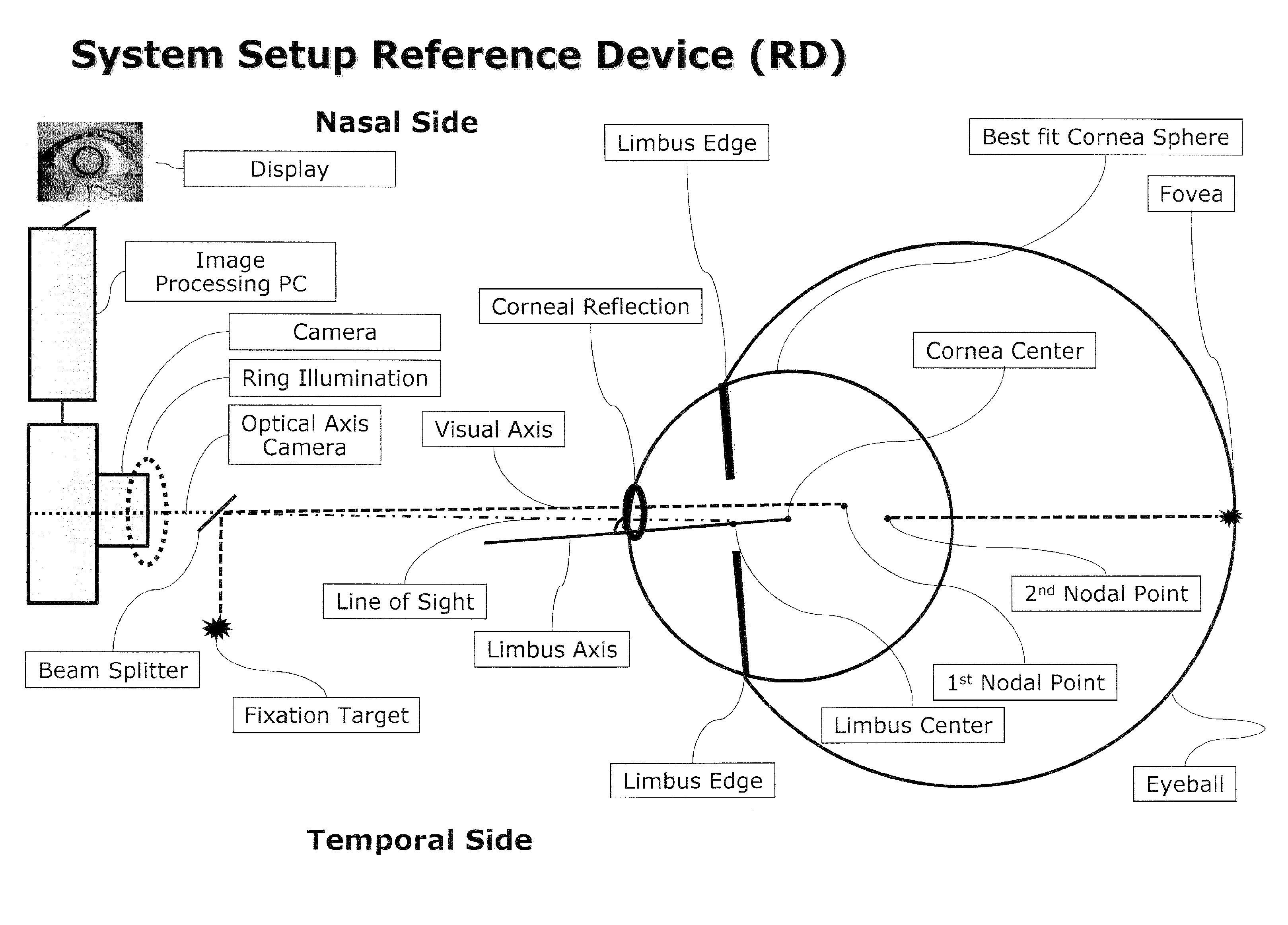
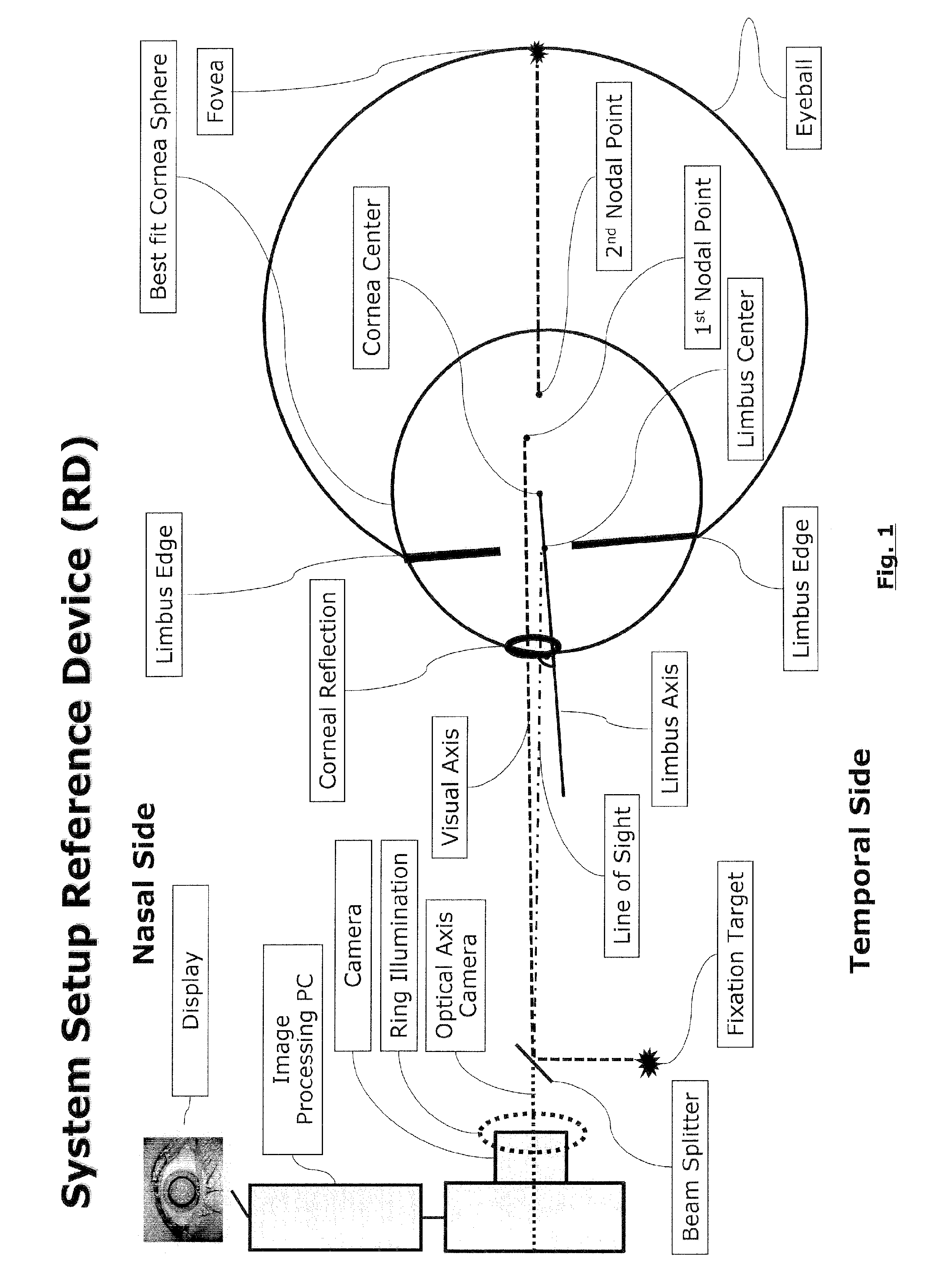
[0076]For pre and post surgery measurements according to one embodiment the solution described here uses a specific apparatus hereinafter called a ‘Reference Device’ (RD) which consists of a PC connected to a digital camera and an illumination system on a cross table which allows capturing a high resolution color image of a patients eye in a defined position. The apparatus according to one embodiment and its use in connection with an eye is schematically illustrated in FIG. 1.

[0077]The illumination system of th...


PUM


Abstract

An apparatus for monitoring one or more parameters of the eye of a patient over multiple sessions which are temporally spaced apart and between which the eye of the patient can have moved, said apparatus comprising: a camera for taking one or more images of the eye; an illumination unit for illuminating the eye by a ring-shaped light pattern to generate corneal reflections, said illumination unit being preferably located such that the center of the ring is coaxial with the optical axis of the camera; a module for determining during a first session the location of the corneal reflections in the image of the eye; a module for determining during said first session based on said determined location of the corneal reflections, at least one further parameter of the eye and its coordinates in a first coordinate system based on a geometrical model representing the eye as a spherical eyeball having a spherically shaped cornea mounted thereon; a module for determining during a second session temporally spaced apart from said first session said location of said corneal reflections of the eye and based thereon said further eye parameter and its coordinates in a second coordinate system; a module for determining the eye motion in six degrees of freedom between said first and said second session and for determining a coordinate transformation based thereon; a module for transforming based on said determined eye motion said further eye parameter and its coordinates from said first coordinate system into said second coordinate system; a module for quantifying and / or visualizing the change of said further eye parameter between said first and said second session based on said further parameter and its coordinates measured during said second session and said transformed parameter and its coordinates measured during said first session.

Description

CROSS-REFERENCE TO RELATED APPLICATIONS[0001]This application is a U.S. national phase application of co-pending international patent application number PCT / EP2012 / 070848, filed Oct. 22, 2012, which claims priority to European Application No. 11186270.2, filed Oct. 22, 2011, the disclosures of which are incorporated herein by reference.FIELD OF THE INVENTION[0002]This Invention relates to an apparatus for monitoring one or more parameters of the eye.BACKGROUND OF THE INVENTION[0003]The invention refers to the field of ophthalmology, specifically refractive eye diagnostic and eye surgery. For most refractive eye treatments[0004](1) pre-surgery diagnostic information of the patient's eye is determined to choose the adequate procedure (e.g. implant vs. laser) and define the individual treatment steps (e.g. where to cut or how to align the implant),[0005](2) the individual surgery treatment is performed inserting refraction correcting implants (e.g. IOL's, corneal inlays) or executing s...

Claims


Application Information

Patent Timeline
Patent Type & Authority Patents(United States)
IPC IPC(8): A61B3/14A61B3/113A61B3/107A61B3/00A61B3/10A61F9/007A61F2/16A61F2/14
CPCA61B3/0025A61B3/1005A61B3/107A61B3/113A61F2/14A61F2/16A61F9/007A61B3/10A61B3/152A61F2/142
Inventor KERSTING, OLIVERGRUNDIG, MARTIN
Owner ALCON INC
Learn More