Supercharge Your Innovation With Domain-Expert AI Agents!

LED light engine/heat sink assembly

Active Publication Date: 2015-09-08
CONSUMER LIGHTING (U S) LLC
View PDF28 Cites 2 Cited by
  • Summary
  • Abstract
  • Description
  • Claims
  • Application Information

AI Technical Summary

Benefits of technology

The patent describes a light emitting diode (LED) light engine and a method for making it. The LED light engine has LED devices on a front side of a substrate, and a heat sink with a mating receptacle for the LED light engine. The substrate and the heat sink have a tapered fitting that securely holds the light engine in place. The technical effect of this design is improved thermal performance and stability, which allows for better performance and longer lifespan of the LED light engine.

Problems solved by technology

At these low operating temperatures, the radiative heat transfer pathway to the ambient is weak compared with that of conventional light sources, so that convective and conductive heat transfer to ambient typically dominate over radiation.

Method used


Image

  • LED light engine/heat sink assembly
  • LED light engine/heat sink assembly
  • LED light engine/heat sink assembly

Examples


Embodiment Construction

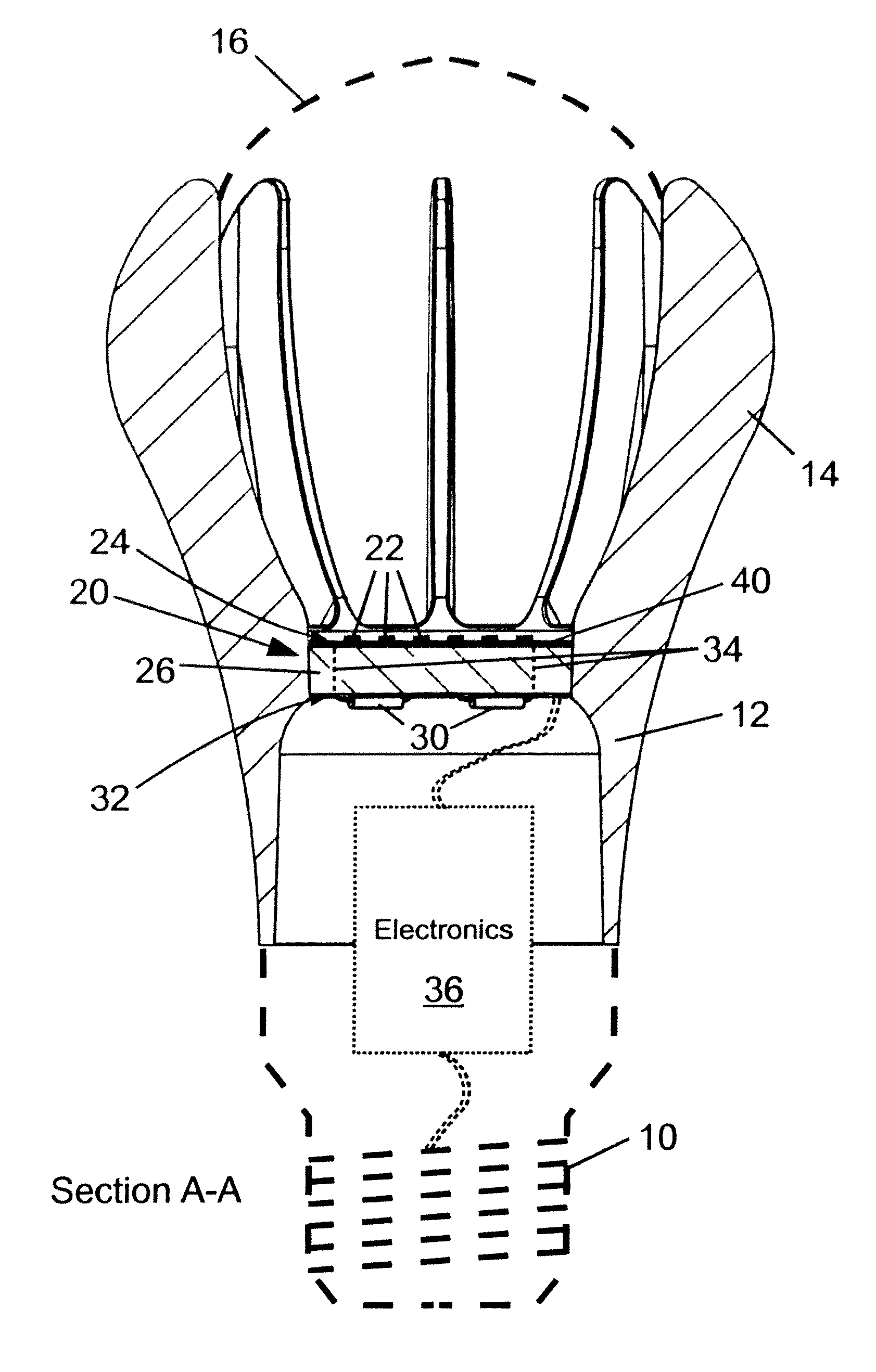
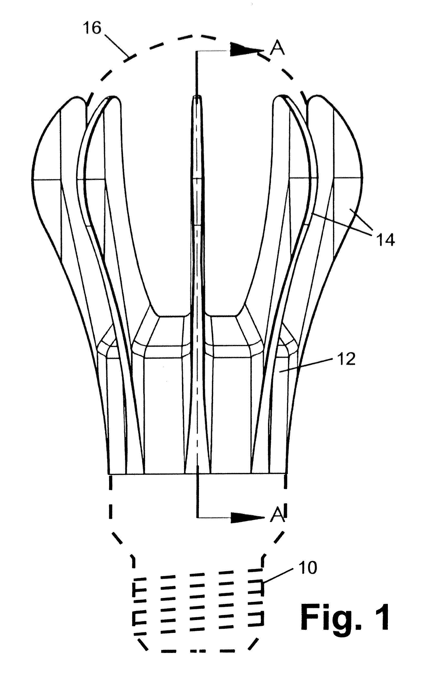
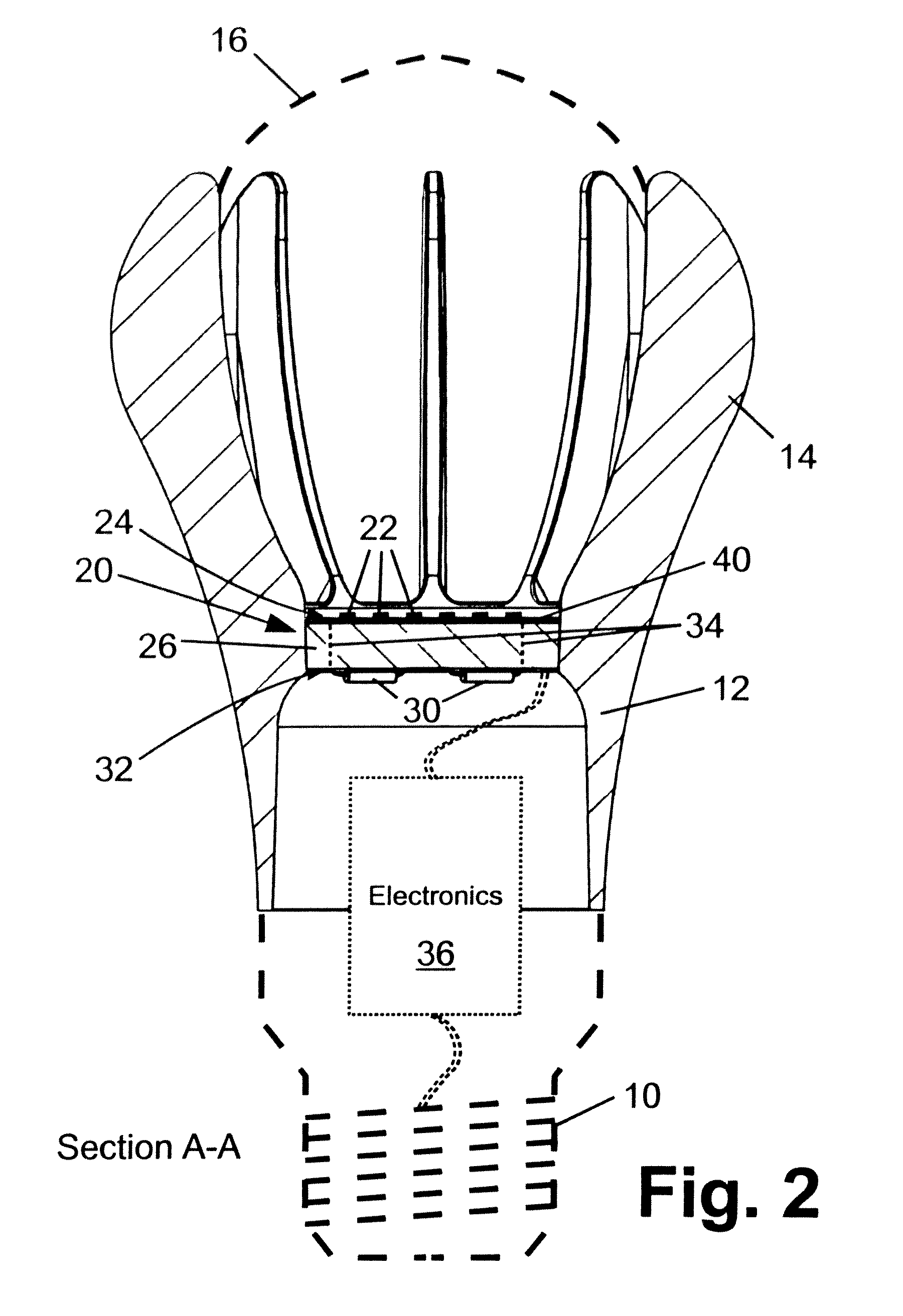
[0015]With reference to FIG. 1, an illustrative lamp is shown. The illustrative lamp has an A-line configuration, with an outer profile corresponding to that of a conventional incandescent “light bulb” of the type used in the 40-100 W electrical input power range or higher. FIG. 1 shows the illustrative lamp while FIG. 2 shows a side sectional view of the lamp (Section A-A indicated in FIG. 1). The lamp includes a base 10 which in the illustrative view is an Edison-type threaded or “screw-in” base whose outline is shown in phantom (that is, using dashed lines) in FIGS. 1 and 2. The main body of the lamp is defined by a heat sink 12 having fins 14 and by an optical diffuser 16. Like the lamp base 10, the outline of the optical diffuser 16 is shown in phantom in FIGS. 1 and 2. The diffuser 16 may have a spherical shape ovoid shape, egg-shape (a combination of prolate ovoid and oblate ovoid shapes), a “bulb” shape (mimicking the shape of the glass bulb of a conventional incandescent li...


PUM

PropertyMeasurementUnit
taper angleaaaaaaaaaa
temperatureaaaaaaaaaa

Abstract

According to a first embodiment, a light emitting diode (LED) light engine is described. The light emitting diode includes one or more LED devices disposed on a front side of an LED light engine substrate. A heat sink having a mating receptacle for the LED light engine is also provided. The LED light engine substrate and the mating receptacle of the heat sink define a tapered fitting by which the LED light engine is retained in the mating receptacle of the heat sink.

Description

[0001]This application claims the benefit of U.S. Ser. No. 61 / 434,048 filed Jan. 19, 2011. The disclosure of which is herein incorporated by reference.BACKGROUND[0002]The following relates to the illumination arts, lighting arts, solid state lighting arts, lamp and luminaire arts, and related arts.[0003]Conventional incandescent, halogen, and high intensity discharge (HID) light sources have relatively high operating temperatures, and as a consequence heat egress is dominated by radiative and convective heat transfer pathways. For example, radiative heat egress goes with temperature raised to the fourth power, so that the radiative heat transfer pathway becomes superlinearly more dominant as operating temperature increases. Accordingly, thermal management for incandescent, halogen, and HID light sources typically amounts to providing adequate air space proximate to the lamp for efficient radiative and convective heat transfer. Typically, in these types of light sources, it is not ne...

Claims


Application Information

Patent Timeline
Patent Type & Authority Patents(United States)
IPC IPC(8): F21S4/00F21V19/00F21K99/00F21V29/00F21V21/00F21V29/74F21V29/78H01R33/00F21Y101/02
CPCF21K9/135F21V19/003F21V19/0035F21V29/004F21V29/74F21V29/78F21Y2101/02Y10T29/49945F21K9/232F21Y2115/10F21V29/713F21K9/23
Inventor KUENZLER, GLENN H.HUDDLESTON, II, CHARLES L.MARTINS, JEREMIAS A.CHOWDHURY, ASHFAQUL I.ALLEN, GARY R.
Owner CONSUMER LIGHTING (U S) LLC
Features
  • R&D
  • Intellectual Property
  • Life Sciences
  • Materials
  • Tech Scout
  • Unparalleled Data Quality
  • Higher Quality Content
  • 60% Fewer Hallucinations
Learn More