
Adjustment device for guide rollers and relative adjustment method

a technology of adjustment device and guide roller, which is applied in the direction of guiding/positioning/aligning arrangement, metal rolling, manufacturing tools, etc., can solve the problems of inability to control and predict the movement of the rolling roll, and the inability to accurately center the metal product. achieve the effect of increasing the functional precision of the devi

Inactive Publication Date: 2015-09-15
DANIELI & C OFF MEC SPA
View PDF7 Cites 0 Cited by
  • Summary
  • Abstract
  • Description
  • Claims
  • Application Information

AI Technical Summary

Benefits of technology

[0026]With the present invention, the guide rollers both move by the same amount with respect to the nominal rolling axis, thus guaranteeing an effective, constant and precise adjustment of the distance between the two guide rollers, and guaranteeing a correct, centered positioning of the metal product with respect to the rolling axis.
[0030]In this way it is possible to determine in advance, and with greater accuracy, the final positioning of the guide rollers on the metal product, without considering factors connected to the inclination of the movement or other.
[0038]In this way, the functional precision of the device is increased.

Problems solved by technology

This known solution has considerable disadvantages in the coordination of the actuators, with greater inaccuracies of positioning and centering of the metal product with respect to the work rolls and to the rolling axis.
However, this known solution, as well as having disadvantages connected to the coordination of the actuators, in any case does not guarantee a sufficiently accurate centering of the metal product with respect to the rolling axis, since it has to provide independent feeds for the actuators.
In this type of known solution, the movement of the rolling rolls, which occurs in an inclined direction with respect to the axis, is not easily controllable and predictable, in that the final position of the guide rollers depends, on each occasion, on different geometric factors, among which the angle of movement, the actual size of the metal product and others.
This solution is thus difficult to operate and manage, and has high manufacturing costs due mainly to the need to provide inclined guides or conical parts mating with each other, with complex actuation mechanisms.

Method used


Image

  • Adjustment device for guide rollers and relative adjustment method
  • Adjustment device for guide rollers and relative adjustment method
  • Adjustment device for guide rollers and relative adjustment method

Examples


Embodiment Construction

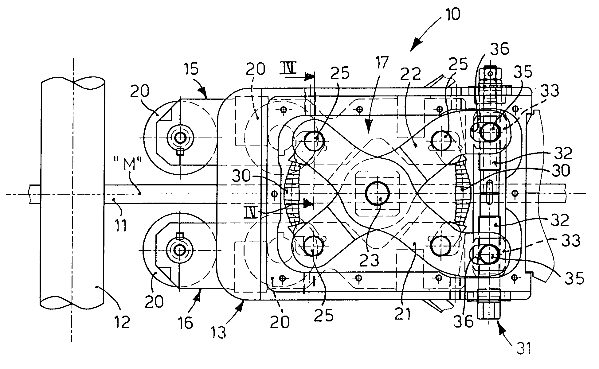
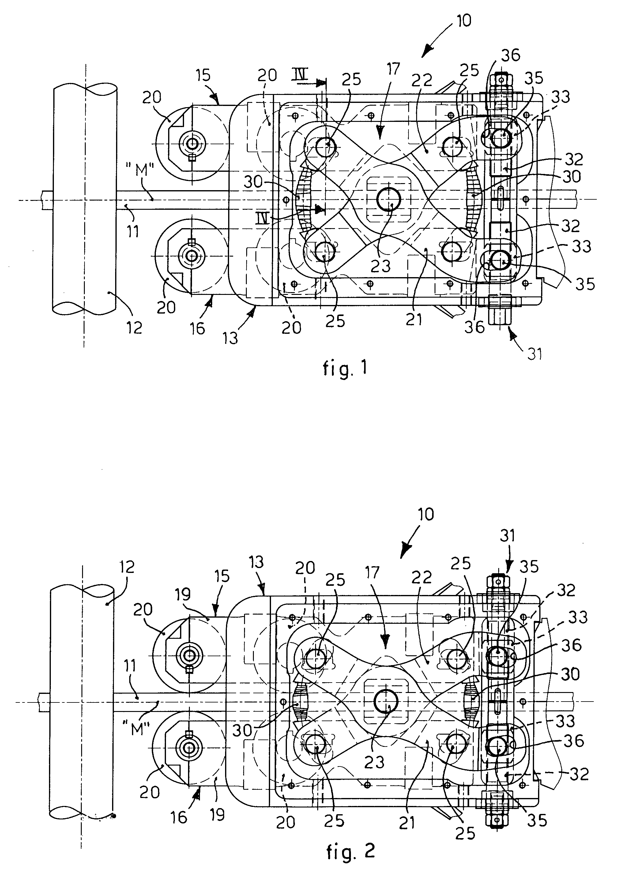
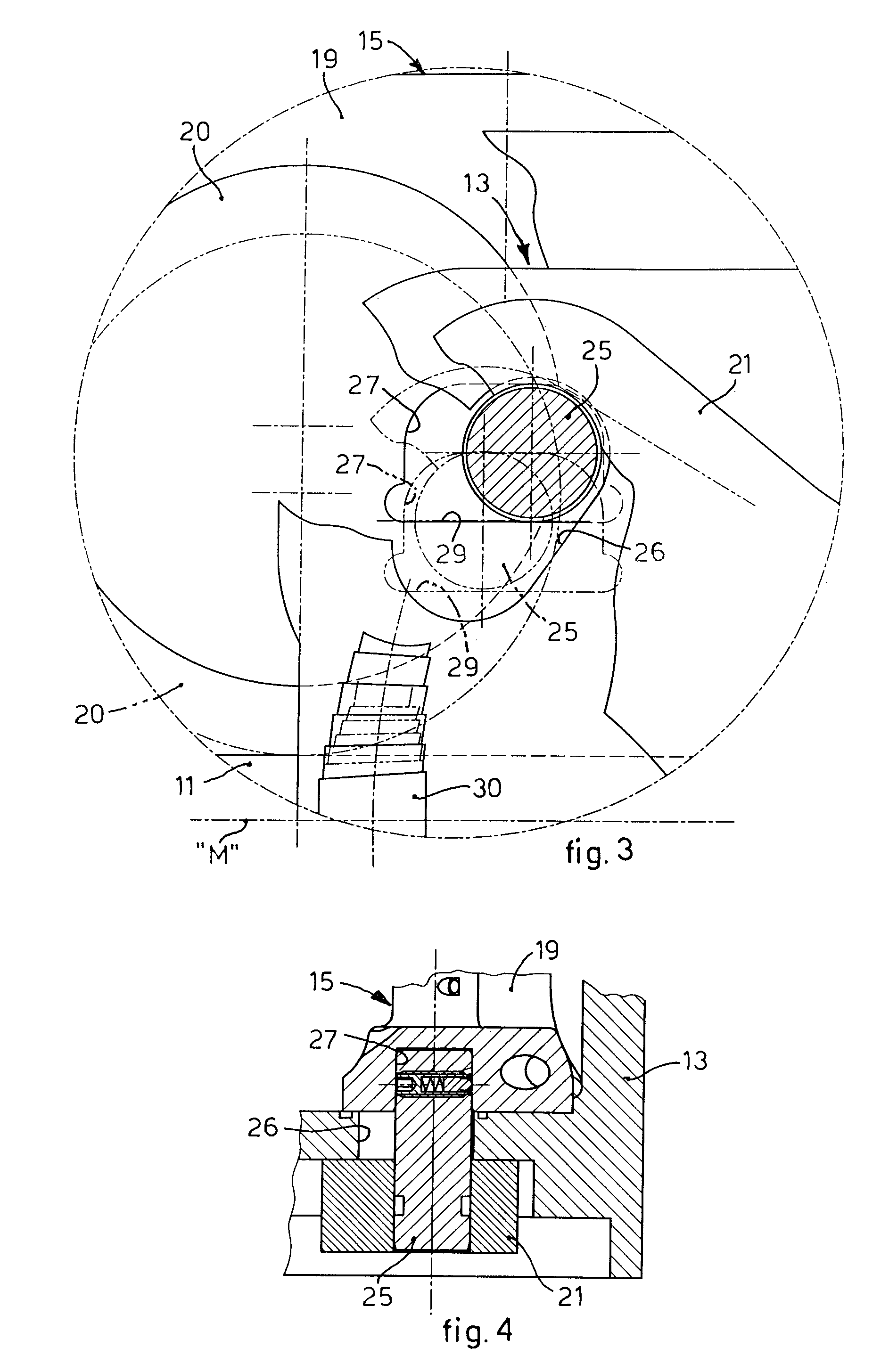
[0046]With reference to the attached drawings, an adjustment device 10 according to the present invention can be installed upstream of a rolling stand to convey a metal product 11 between two work rolls 12 of said rolling stand, along a determinate nominal rolling axis “M”.

[0047]The adjustment device 10 according to the invention comprises a central body 13, two roll bearers 15 and 16, or guide units, and an adjustment mechanism 17.

[0048]The central body 13 is hollow axially in through manner, so as to allow the metal product 11 to pass inside it.

[0049]Advantageously, the central body 13 is positioned substantially astride the rolling axis M, so that the latter substantially coincides with a median longitudinal axis of the axial cavity of the central body 13.

[0050]The roll bearers 15 and 16 are mounted movable on the central body 13, on opposite sides with respect to the rolling axis M.

[0051]Each roll bearer 15, 16 comprises a support bar 19 mounted movable laterally to the central ...


PUM

PropertyMeasurementUnit
movementaaaaaaaaaa
shapeaaaaaaaaaa
relative movementaaaaaaaaaa

Abstract

An adjustment device and method to guide a metal product along a determinate nominal rolling axis. The device comprises a central body disposed astride the rolling axis, two guide units mounted movable on the central body, opposite each other with respect to the rolling axis and each provided with at least a guide roller for the metal product, and an adjustment mechanism mounted on the central body and operatively connected to both the guide units, in order to actuate the selective movement thereof with respect to the central body at least in an approach toward the rolling axis. The adjustment mechanism comprises a system of pantograph levers having two levers pivoted to each other and to the central body in correspondence to the rolling axis by means of a pin, and first constraint means disposed on each lever on opposite sides to the pin, so as to connect each lever to both the guide units.

Description

FIELD OF THE INVENTION[0001]The present invention concerns a device, and relative method, to adjust the position of relative guide rollers used to convey a metal product between two work rolls of a rolling stand, during hot- or cold-rolling operations. In particular the present invention is applied to move the guide rollers coordinately, in order to guarantee the correct centered position of the metal product with respect to the axis of the rolling channel defined by the work rolls.BACKGROUND OF THE INVENTION[0002]In the field of rolling, the need to correctly direct the metal product entering between the work rolls of a rolling stand is known.[0003]This need is even more urgent in the case of rolling long products such as bars, metal wire or other, in which the work rolls are shaped in a coordinate and complementary way to the section of the rolled product.[0004]Generally, to guarantee the centering of the rolled product with respect to the rolling channel defined by the work rolls...

Claims


Application Information

Patent Timeline
Patent Type & Authority Patents(United States)
IPC IPC(8): B21B39/16B21B19/12
CPCB21B39/165B21B19/12
Inventor IOGNA PRAT, EMANUELEDI GIACOMO, MARCO
Owner DANIELI & C OFF MEC SPA
Learn More