Fuel filter and mounting support of which the outlet is sealed by a valve in case of removal of a filter insert

a technology of fuel filter and mounting support, which is applied in the direction of membrane technology, filtration separation, separation process, etc., can solve the problems of stalling, direct freeing of clean fuel outlet pipe, contamination of outlet pipe,

Active Publication Date: 2022-05-24
SOGEFI FILTRATION
View PDF14 Cites 0 Cited by
  • Summary
  • Abstract
  • Description
  • Claims
  • Application Information

AI Technical Summary

Benefits of technology

[0021]With these arrangements, the actuating member moves the valve according to the position of the filter insert: the closed position can then be obtained by removing the cover with the associated removal of the filter insert. The unfiltered fuel then cannot drain towards the outlet and thus, by integrating an actuating member into the central part of the filter, the risk of contamination of the outlet by unfiltered fuel is minimized or eliminated.
[0022]In addition, the transverse wall defines a passage for conveying gases contained in the fuel to an escape channel that is distinct from the inlet and the outlet. The conditions for replacing the filter insert are thus improved, while enabling an efficient venting of the gases contained in the fuel.
[0040]the connection interface comprises a portion sealingly engaged against the annular wall by an annular and preferably radial contact, and a sleeve extending into the hollow internal space (reaching or exceeding half the height of the filter insert in the mounted position) and of which the bottom defines the passageway; thus the sleeve forms a barrier preventing the unfiltered fuel present around the filter medium from flowing under the filter insert towards the passageway, which is important during the short time where the filter insert is no longer in contact with the connection interface but the valve has not yet reached the closed position.
[0044]the second end of the actuating member comprises a free end adapted to sealingly engage with a tubular coupling formed in the transverse wall, and at least one stop member, preferably a collar, for axially engaging the longitudinal projection while pushing the valve and also for engaging the coupling; the actuating member thus has a robust configuration, being protected within the hollow internal space and being rigidly attached to a connection interface (with a radial contact combined with an axial contact against the interface, stresses on the actuating member are minimized, which is advantageous in an environment subject to vibrations when the vehicle is in motion).
[0058]Thus, a new function for a filter insert is added, with the added possibility for the lower axial end of the filter insert to act as actuator for a closure member, typically in order to close a purge channel for unfiltered fuel. Positioning of the filter insert associated with the piping member is permitted where appropriate without the need for any rotational indexing, which is advantageous for the operator (time is saved in installing the removable unit defined by the filter insert and piping member). The use of a sleeve in the coupling interface of the mounting support is an option which further facilitates the correct centered position of the piping member.

Problems solved by technology

When using a filter under negative pressure, the negative pressure due to suction of the fuel causes cavitation.
The presence of a small port prevents large air bubbles from entering the pump, which would result in its stalling.
Moreover, a disadvantage of this type of filter insert is that it directly frees the clean fuel outlet pipe when it is removed.
This can cause contamination of the outlet pipe by unfiltered fuel during a filter insert replacement operation.

Method used


Image

  • Fuel filter and mounting support of which the outlet is sealed by a valve in case of removal of a filter insert
  • Fuel filter and mounting support of which the outlet is sealed by a valve in case of removal of a filter insert
  • Fuel filter and mounting support of which the outlet is sealed by a valve in case of removal of a filter insert

Examples


Embodiment Construction

[0067]In the various figures, identical references indicate identical or similar elements.

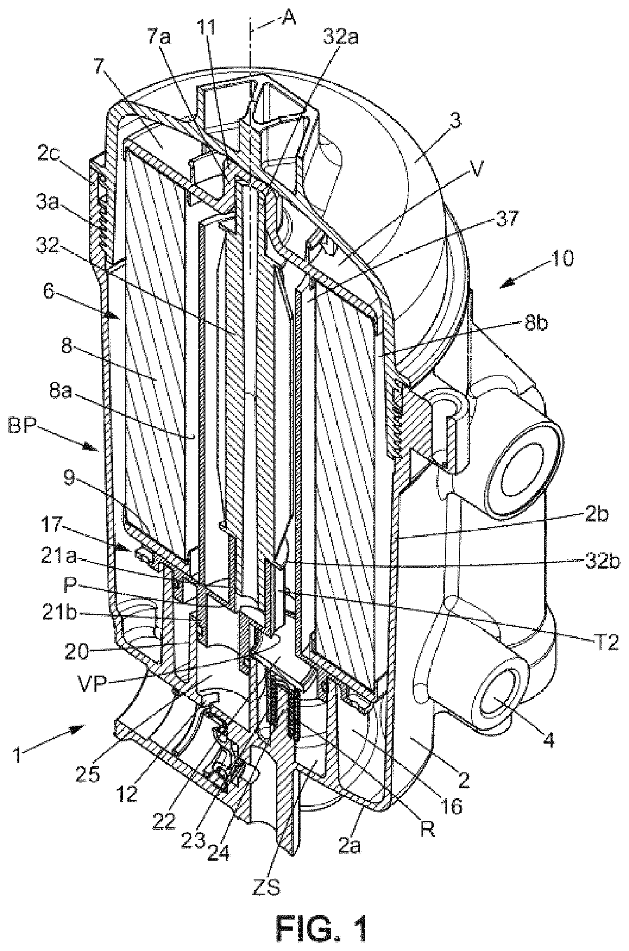
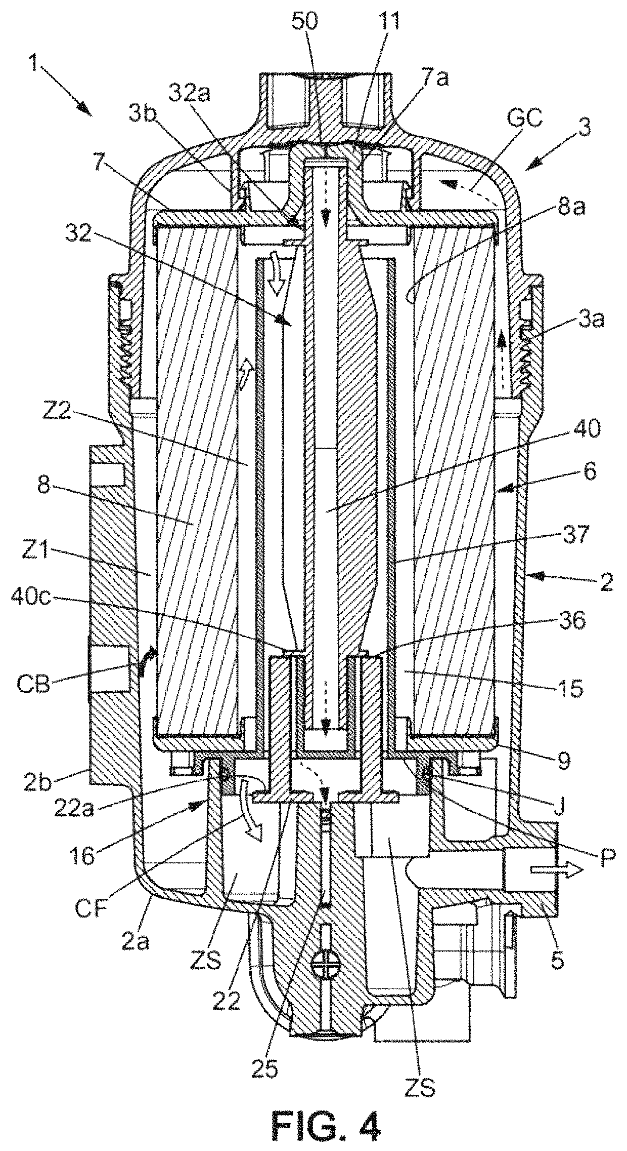
[0068]FIGS. 1 and 4 represent an embodiment of the fuel filter 1 (for diesel or similar fuel) which has venting means for the gases contained in the fuel which extend between a gas capturing upper end 11 and a gas venting lower end 12. This filter 1 comprises a receptacle 10 in the form of a housing which is for example in two parts. The receptacle 10 has a bottom wall and a top wall (here formed by a cover 3 or similar closing wall). In the non-limiting example of the figures, the bottom wall is formed by a bowl 2 typically made of metal or plastic. The bowl 2 has a base 2a from which a side wall 2b extends upwardly, here substantially cylindrical and having an upper end portion 2c directly integral to the cover 3. The cover 3, forming the upper wall of the housing, is directly attached to the bowl 2. More generally, it is understood that the cover 3 is sealingly connected to the bowl 2.

[0069]...


PUM

PropertyMeasurementUnit
diameteraaaaaaaaaa
diameteraaaaaaaaaa
sizeaaaaaaaaaa

Abstract

The fuel filter has an outlet for the filtered fuel in a lower base portion of a casing, and a valve associated with the outlet. The filter insert has an internal space in which filtered fuel flows and that accommodates a central member capable of moving the valve to an open position when the insert is in an operational configuration in the casing. The valve is urged, by default, to a sealed position cutting off the flow to the outlet, for example by resilient return arranged between the bottom of the filter and a wall of an interface that guides the lower end of the central member. The central member and the filter insert form a removable unit, and it is therefore possible, typically by way of a cover / removable unit fastening, to automatically obtain the sealed position after opening the top cover.

Description

TECHNICAL FIELD OF THE INVENTION[0001]The present invention relates to fuel filters for internal combustion engines, particularly to diesel filters having a filter insert that is removable from a filter housing.BACKGROUND OF THE INVENTION[0002]A fuel filter of the above type typically comprises a fuel inlet and outlet defined by the housing, and a filter insert housed inside the housing so as to define an upstream region of unfiltered fuel which communicates with the inlet and a downstream region of filtered fuel which communicates with the outlet. In a diesel fuel supply system for a diesel engine, this type of filter allows filtering the diesel fuel to eliminate impurities and optionally to separate out water in suspension. In a motor vehicle, the fuel supply system comprises a fuel filter, an injection pump, and a fuel circulation pump (or priming pump) which can be placed upstream of the filter (then referred to as a “booster pump”), the filter then operating under positive pres...

Claims


Application Information

Patent Timeline
Patent Type & Authority Patents(United States)
IPC IPC(8): B01D35/157B01D36/00B01D35/153B01D29/15B01D35/16B01D29/21B01D35/00
CPCB01D35/1573B01D29/15B01D29/21B01D35/005B01D35/153B01D35/1576B01D35/16B01D36/001B01D2201/16B01D2201/291B01D2201/305B01D2201/316B01D2201/347
Inventor FAYOLLE, LAURENTLALLEMAN, XAVIER
Owner SOGEFI FILTRATION
Why Eureka
Try Eureka