Catheter decoupling device

a catheter and decoupling technology, applied in the field of catheter decoupling devices, can solve the problems of ineffective nerve block, tissue tear and/or distal end migration, and inability to effectively relieve pain, so as to reduce the risk of stressing the anchor site at either end or eliminate the effect of stressing the risk

Active Publication Date: 2020-01-28
SRI INTERNATIONAL
View PDF2 Cites 0 Cited by
  • Summary
  • Abstract
  • Description
  • Claims
  • Application Information

AI Technical Summary

Benefits of technology

[0006]The invention provides a decoupling system that allows a limited range of motion of the proximal end of the catheter. The decoupling system may be located between the proximal end of the catheter and the utility tubing and may be coupled or attached temporarily to the skin at the catheter exit site. This configuration allows a catheter with anchored at both ends to be utilized as the risk of stressing the anchor sites at either end is minimized or eliminated. This configuration also allows the length between the distal anchor site and the proximal anchor site to change allowing the patient to ambulate without risk of the catheter dislodging. The decoupling mechanism may also be able to absorb external forces and impacts, such as changing of the utility tubing or accidental pulling of the utility tubing. The decoupling mechanism may be designed to have varying amounts of motion. The range of distance that the decoupling mechanism allows may differ by application, location on body and purpose. The predetermined allowed range of motion in the decoupling motion may range from zero to the maximum anticipated distance needed for each particular application. For example, in femoral nerve blocks one can expect larger motion during hip flexion, so the range of motion that the decoupler needs to handle is larger than, for example, the range of motion you might expect to need to handle in an interscalene brachial plexus block. In most continuous peripheral nerve blocks, the distance that the proximal end of the catheter may be allowed to change between zero to five centimeters. In addition to being able to accommodate patient ambulation, the decoupling mechanism described below allows for different sized catheters. For example, in the embodiment with a sled that moves within a channel, one can adjust the channel length, for example, to create varying “size” decouplers for different medical applications.
[0010]the minimization or prevention may be achieved by a decoupling device that may generally consist of a mechanism that prevents or minimizes motion of the proximal end of the catheter. In an embodiment the mechanism comprises coupling the proximal end of a catheter to a movable platform which in turn may be coupled to tubing that can flex and / or stretch so that the motion of the entities may be taken up by the tubing rather than the proximal end of the catheter. Further, in addition to being able to move lengthwise, the movable platform may have the ability to move side to side or up and down to accommodate the various motions that the proximal end may encounter;
[0025]the proximal end of the hub is configured to receive the catheter fluid supply device via a flexible or stretchable tubing connected to the hub via a connector and connected to the catheter fluid supply device via an inlet port, wherein the catheter fluid supply device is one of multiple (such as 2, 3, 4, 5 or 6) fluid supply devices, and the inlet port is one of multiple (such as 2, 3, 4, 5 or 6) inlet ports (see, e.g. FIG. 7), which may be connected to corresponding multiple lumens of the catheter, wherein each lumen terminates in a distinctly located exit port; see, e.g. FIGS. 8A, 8B; and / or wherein the catheter comprise at least inner and outer multimaterial sheaths, wherein the inner surface of the inner sheath comprises a lubricious material (e.g. PTFE), and / or wherein the inner sheath comprises an embedded coil (providing echogenicity, anti-kinking properties, rigidity, durability and / or strength).

Problems solved by technology

If migration occurs, the nerve block may become ineffective and the pain symptoms may return.
This may lead to tissue tear and or migration of the distal end; in this case the block may become ineffective.
On the proximal side, tissue bruising may occur which may lead to further complications.

Method used


Image

  • Catheter decoupling device
  • Catheter decoupling device
  • Catheter decoupling device

Examples


Embodiment Construction

THEREOF

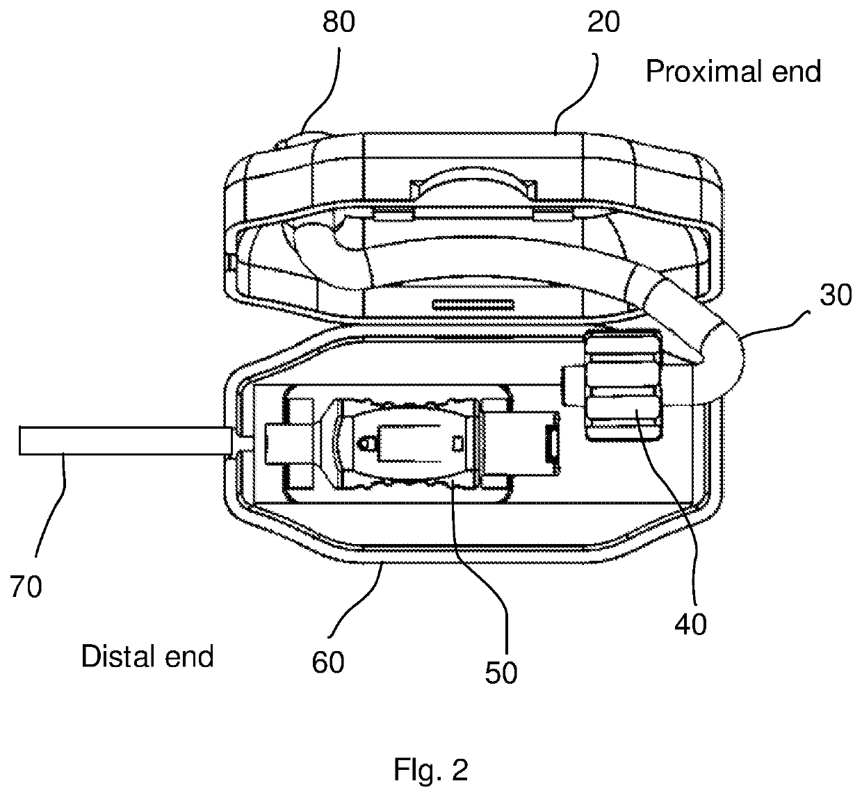
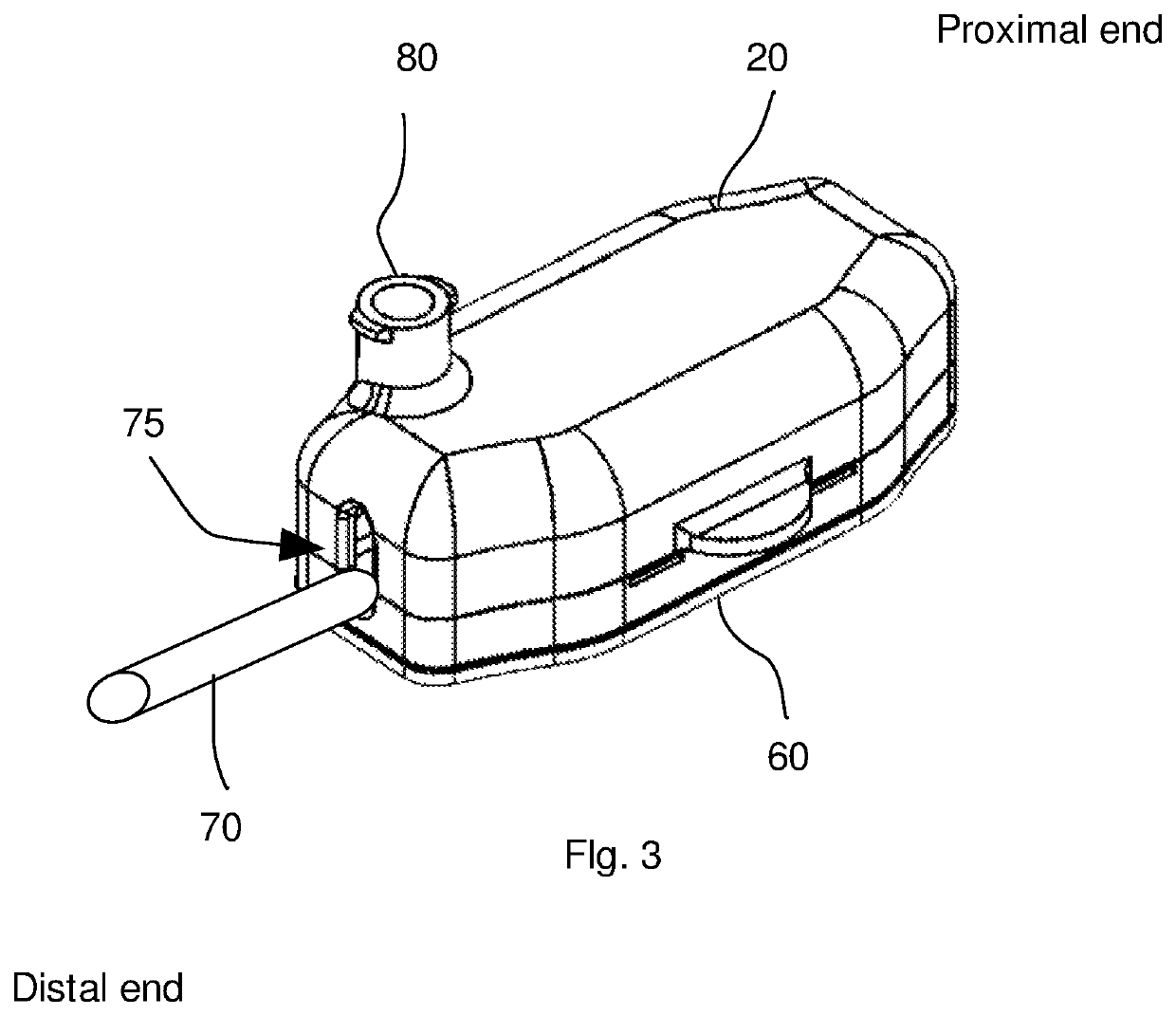
[0036]FIG. 1 illustrates one configuration of the decoupler, 10. This decoupler may be placed proximal to the exit location of an embedded catheter, between the catheter and the utlity tubing or other delivery devices. In this configuration, the catheter 70 may be coupled to a catheter hub 50. The catheter hub 50 may be placed within a sled 25; the distal and the proximal ends of the sled are visible in the figure and are both enumerated as 25. The sled may be positioned on a track 35 such that the sled may have some freedom of movement generally between the proximal end and the distal end of the decoupler. The track may be also so designed that some freedom of motion may be allowed side to side. In some versions, the tracks may be further designed to allow some up and down motion a well. As will be evident as more of the decoupler is described, this freedom of motion imparted to the sled is one component of the design of the decoupler that prevents, minimizes or eliminates m...


PUM


Abstract

Devices, systems and methods are used to decouple proximal movement of a catheter supply lead or tubing from the tissue-embedded catheter. A catheter decoupling device comprises a catheter hub, sled and track, wherein the hub comprises a proximal end configured to receive a catheter fluid supply device, and a distal end configured to receive a catheter, the sled receives and retains the hub, the track receives and retains the hub; and, the hub has a limited range of back-and-forth motion relative to the track.

Description

[0001]This application is a continuation of PCT / US16 / 19954; filed Feb. 26, 2016, which claims priority to Ser. No. 62 / 121,279; filed Feb. 26, 2015.[0002]This invention was made with government support under grant 1P50FD003782 awarded by the Department of Health and Human Services. The government has certain rights in this invention.INTRODUCTION[0003]In the practice of health care, there are numerous procedures where a catheter is placed within the body and is used as a conduit to either deliver therapeutic agents such as but not limited to drugs or to extract bodily fluids such as but not limited to blood. In some cases the catheter is used for both functions; to deliver agents and to extract fluids. In some of these procedures, it is necessary to ensure that the distal tip of the catheter remain stationary or relatively stationary at a particular location within the body. Such situations arise for example when a catheter is used to deliver anesthetic agents to a particular site wit...

Claims


Application Information

Patent Timeline
Patent Type & Authority Patents(United States)
IPC IPC(8): A61M25/00A61M39/10A61M5/168A61M39/20
CPCA61M25/0097A61M39/1011A61M5/16813A61M39/20A61M39/10A61M2025/0098
Inventor HOFIUS, JONATHANQIU, CHUNYUANKOTHARI, MANISH
Owner SRI INTERNATIONAL
Why Eureka
Try Eureka