A closed ring structure for gripping cylindrical workpieces

A closed annular structure, cylindrical technology, applied in workpiece clamping devices, metal processing machinery parts, manufacturing tools, etc., can solve the problem that the center of the item is aligned with the center of the place where it needs to be placed, affecting the production efficiency of processing, The problem of high labor intensity of workers can achieve the effect of convenient and fast grasping process, improve clamping efficiency, and avoid excessive recycling.

Active Publication Date: 2019-04-02
FOSHAN HECAI TECH SERVICE +1
View PDF10 Cites 0 Cited by
  • Summary
  • Abstract
  • Description
  • Claims
  • Application Information

AI Technical Summary

Problems solved by technology

This type of gripper only has the function of grasping and transferring the object, and does not further limit the gripping of the object, and the object is easily affected by the inertia of acceleration or deceleration during the transfer process. The holding center does not coincide with the center of the object, and the object is very easy to drop, which will greatly affect the production efficiency of the processing, and it is easy to damage the held object
[0003] In addition, for grippers that only have a gripping effect, after the gripper grabs the item for transfer, the placement of the item is only in a rough orientation, and the center of the item cannot be aligned with the center of the desired placement, such as placing a cylinder When the workpiece is grasped and transferred, and installed in the corresponding mounting hole, after the cylindrical workpiece is transferred, the worker needs to position and install the workpiece and the mounting hole, the labor intensity of the worker is high, and the processing efficiency is low

Method used


Image

  • A closed ring structure for gripping cylindrical workpieces
  • A closed ring structure for gripping cylindrical workpieces
  • A closed ring structure for gripping cylindrical workpieces

Examples


Embodiment 1

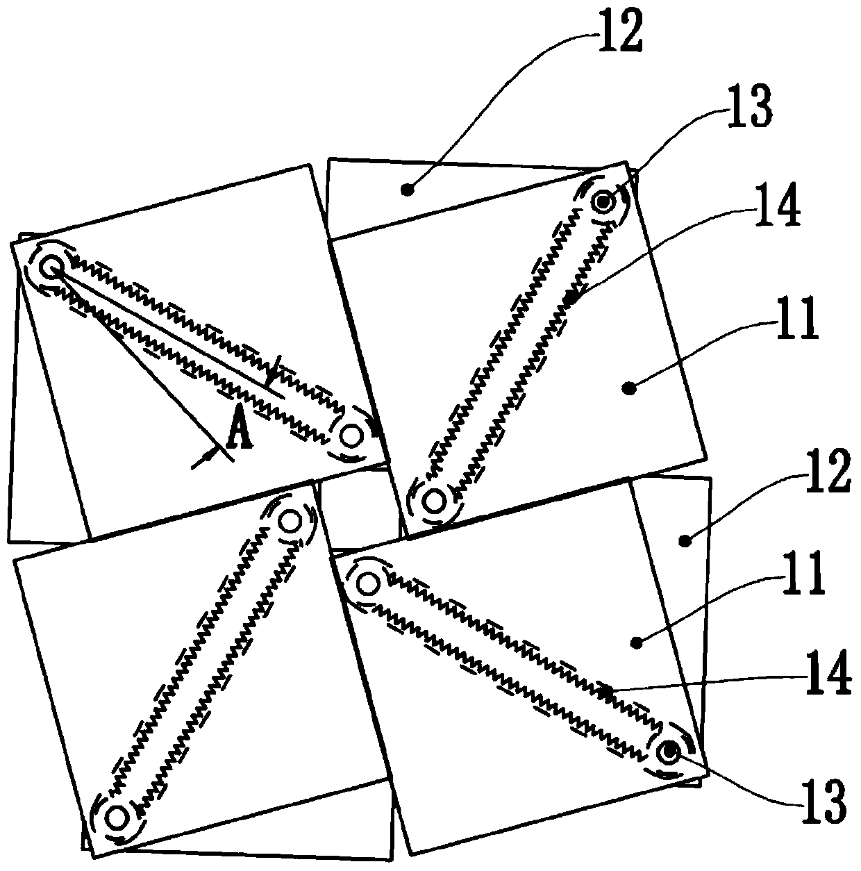
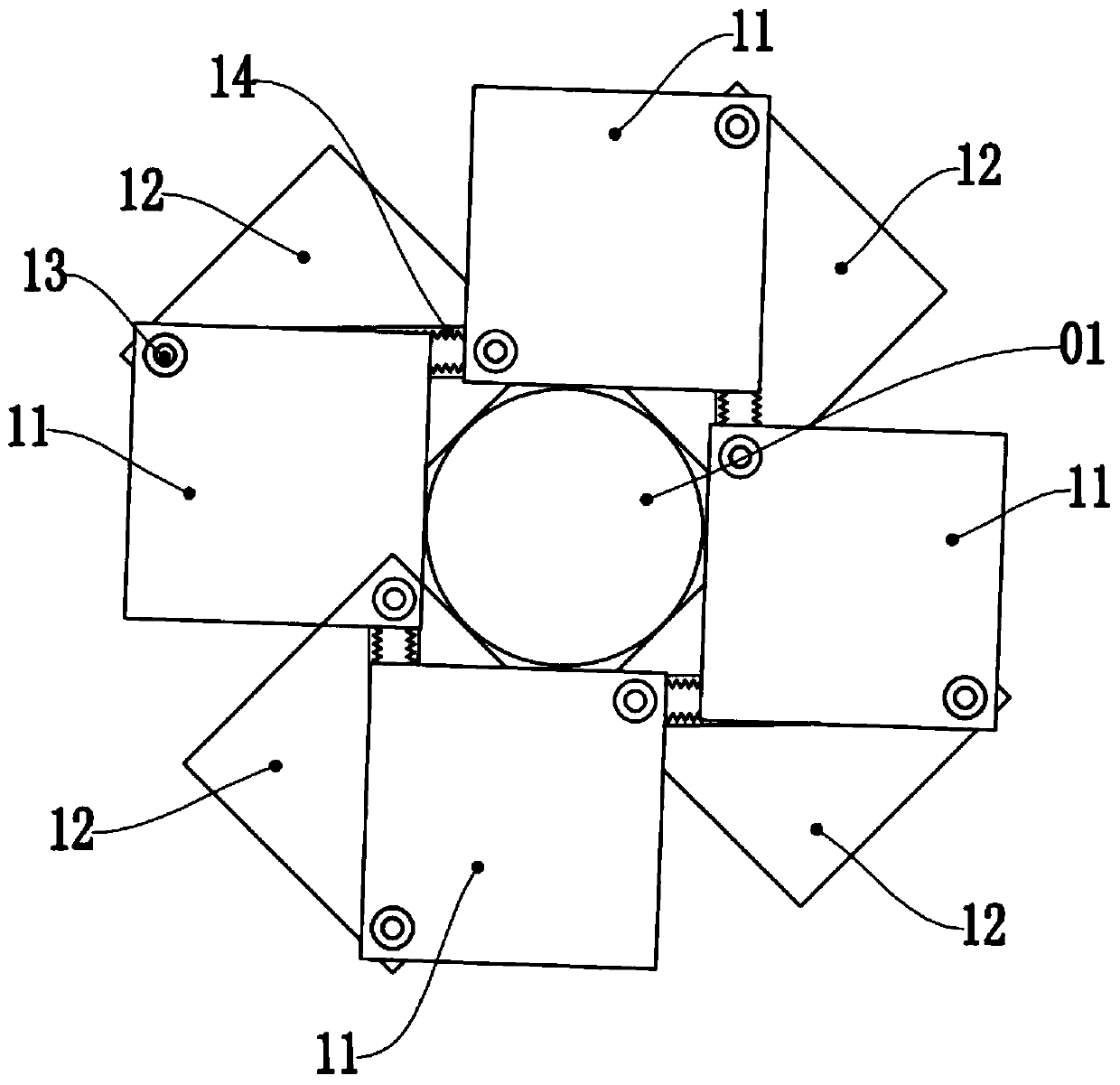
[0038] Example 1, such as image 3 Shown, be provided with 4 groups of square rotating assemblies 1, promptly be provided with 4 upper blocks 11, as Figure 6 As shown, the synchronous transmission assembly 14 is disposed between the upper block 11 and the lower block 12 .

[0039] To further illustrate, the upper block 11 is provided with pulleys 111 at opposite corners of the rotating shaft 13, and the rotating shafts 13 are rigidly connected to the pulleys 111 of the upper block 11 respectively connected to them, so The synchronous transmission assembly 14 is a flexible belt. The upper block 11 is provided with a pulley 111 rigidly connected to the rotating shaft 13, so that the connection between the rotating shaft 13 and the upper block 11 is more stable, the strength of the connection structure becomes larger, and the service life of the entire gripping structure is extended.

[0040] To further illustrate, the pulley 111 is a smooth pulley, and the flexible belt is a ...


PUM


Abstract

A closed ring structure for grabbing a cylinder workpiece comprises upper square blocks, lower square blocks, rotation shafts and synchronous transmission assemblies. The multiple upper square blocks and the multiple lower square blocks are arranged at intervals, conduct surrounding along any one of respective diagonal lines in an end-to-end manner and are rotationally connected at the opposite angle positions through the rotation shafts, and accordingly the closed ring structure is formed. The two rotation shafts arranged on the same lower square block are in rigidity connection to the upper square blocks connected with the rotation shafts, wherein the two rotation shafts are connected through the corresponding synchronous transmission assembly. Rotation of any rotation shaft drives same-direction rotation of the other corresponding rotation shaft through transmission of the corresponding synchronous transmission assembly, unfolding or folding movement of the whole closed ring structure is achieved, and the cylinder workpiece is grabbed in the inner circumference of the closed ring structure. The closed ring structure for grabbing the cylinder workpiece is provided and can change the situation that existing clamps only have a single clamping function, and center alignment positioning can be conducted on the cylinder workpiece.

Description

technical field [0001] The invention relates to the technical field of fixtures, in particular to a closed ring structure for gripping cylindrical workpieces. Background technique [0002] The grippers in the prior art are generally open grippers, that is, open to grasp objects like a human hand. This type of gripper only has the function of grasping and transferring the object, and does not further limit the gripping of the object, and the object is easily affected by the inertia of acceleration or deceleration during the transfer process. If the holding center does not coincide with the center of the object, the object is very easy to drop, which will greatly affect the production efficiency of the processing, and it is easy to damage the held object. [0003] In addition, for grippers that only have a gripping effect, after the gripper grabs the item for transfer, the placement of the item is only in a rough orientation, and the center of the item cannot be aligned with ...

Claims


Application Information

Patent Timeline
Patent Type & Authority Patents(China)
IPC IPC(8): B23Q3/00B25B11/00
CPCB23Q3/00B23Q2703/10B25B11/00
Inventor 不公告发明人
Owner FOSHAN HECAI TECH SERVICE
Why Eureka
Try Eureka