Multilayer video screen

a video screen and multi-layer technology, applied in the field of multi-layer video screens, can solve the problems of reducing the contrast of the rear screen to viewers, difficult to get sufficient backlighting brightness, and the basic form of the multi-layer display as described above suffers from certain problems, so as to achieve the effect of reducing the interference of moistur

Active Publication Date: 2015-09-15
APTIV TECH LTD
View PDF268 Cites 0 Cited by
  • Summary
  • Abstract
  • Description
  • Claims
  • Application Information

AI Technical Summary

Benefits of technology

[0017]Accordingly, in a first aspect the invention may broadly be said to consist in a multi layer display device comprising at least two display layers at least in part overlapping in which at least one of said display layers has a dissimilar configuration to the other display layer(s) such that moiré interference is reduced.

Problems solved by technology

The basic form of the multilayer display as described above suffers from certain problems.
When similar liquid crystal display screens are used for both the front and rear screens the display suffers from a Moiré fringe pattern which makes it unusable.
Another undesirable effect is to reduce the contrast of the rear screen to viewers.
A further problem with the system is that it is difficult to get sufficient brightness from the backlighting for the display.

Method used


Image

  • Multilayer video screen
  • Multilayer video screen
  • Multilayer video screen

Examples


Embodiment Construction

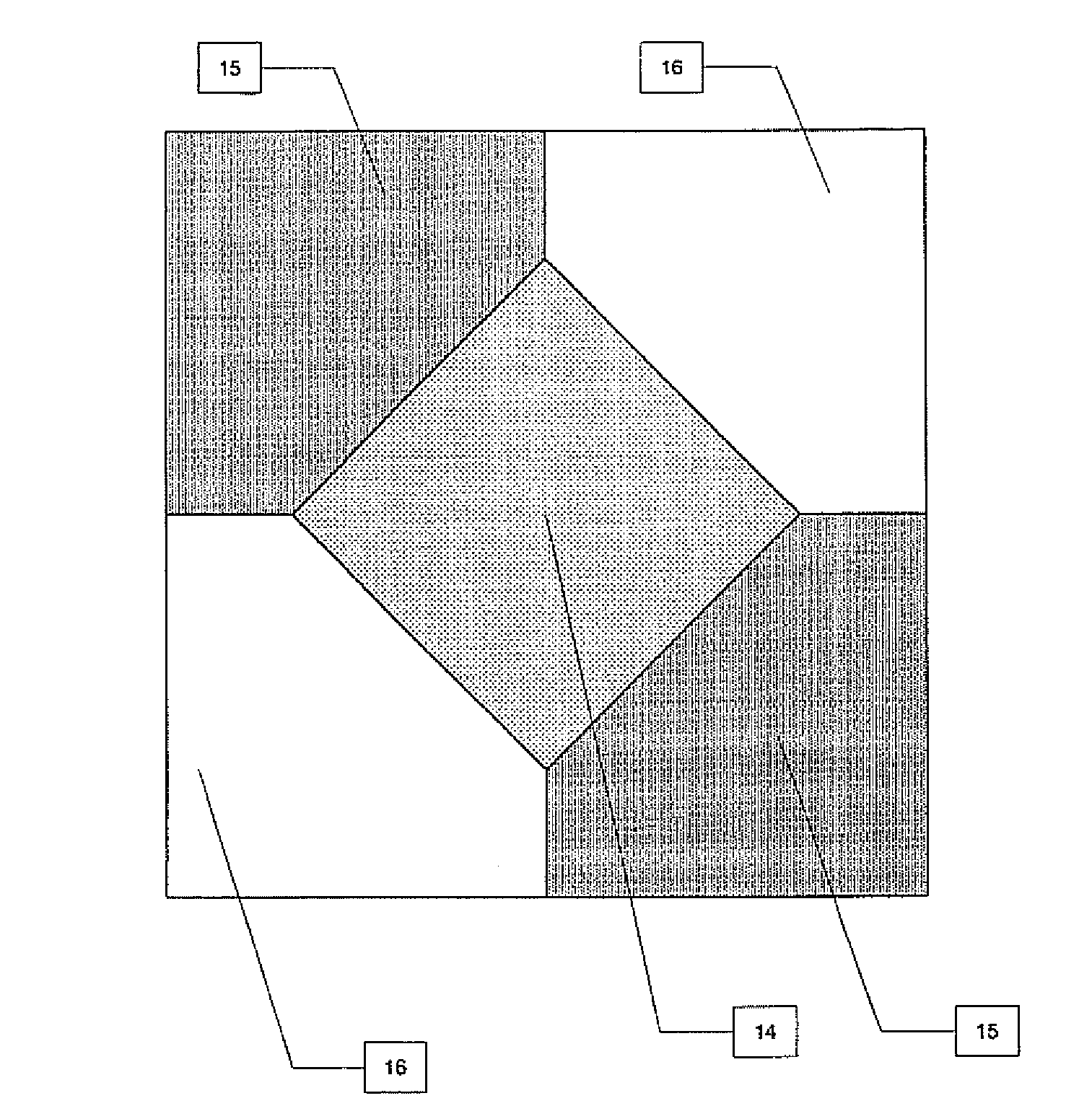
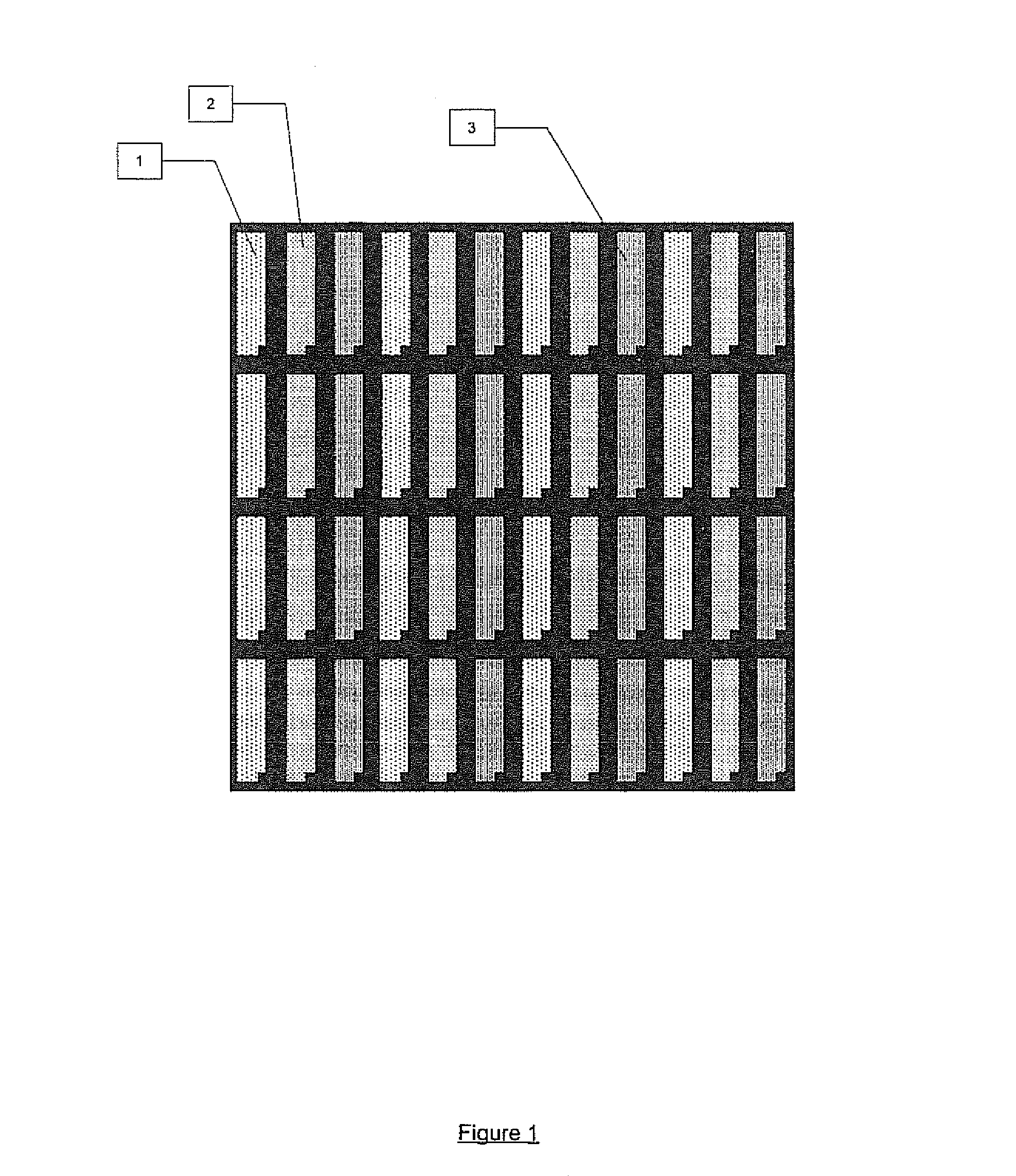
[0078]FIG. 1 illustrates a diagrammatic representation of a typical LCD panel consisting of a tessellated pixel pattern consisting of a red sub pixel (1), a green sub pixel (2), and a blue sub pixel (3).

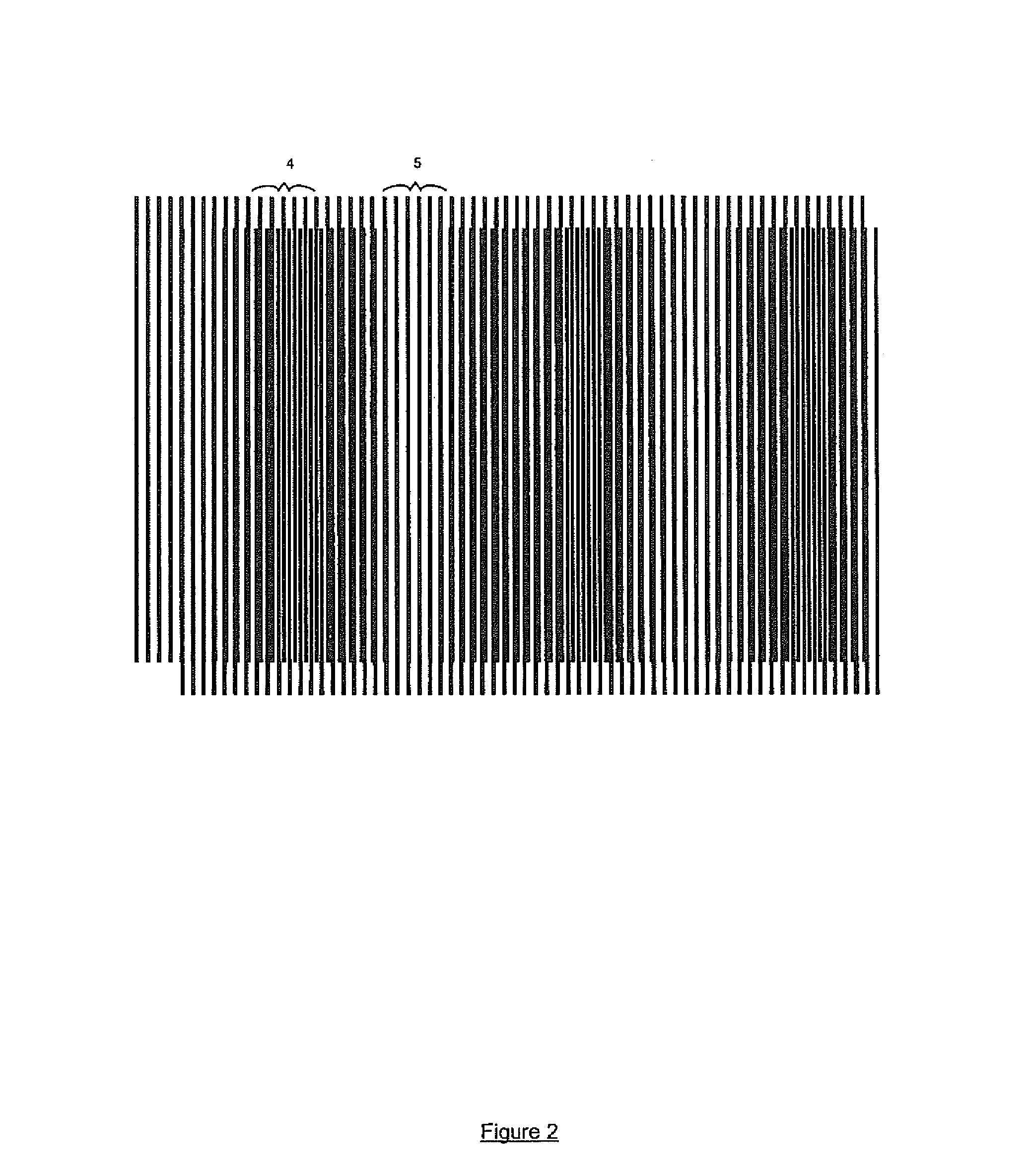
[0079]FIG. 2 illustrates a diagrammatic view of a moiré interference pattern in where the black lines represent one colour from a display layer utilising a stripe pattern pixel overlapping another display utilising a strip pattern pixel. The vertical section delimited by braces shows where the moiré pattern is most dense (4) and the vertical section delimited by braces shows where the interference is least dense (5).

[0080]FIG. 3 illustrates a preferred embodiment of the invention being a multi-layered display composed of a backlight (6) lighting two image formation layers or display layers (7) and (9) both of which are (at least in part) transparent or transmissive to light and interstitial transmissive light diffusing films (8) all of which are co-linear. In a typical embodiment of ...


PUM

PropertyMeasurementUnit
depthaaaaaaaaaa
depthaaaaaaaaaa
refractive indexaaaaaaaaaa

Abstract

A display device comprising at least two display layers at least in part overlapping in which at least one of said display layers has a dissimilar configuration to the other display layer(s) such that moiré interference is reduced.

Description

RELATED APPLICATIONS[0001]This application is a National Stage of International Application No. PCT / NZ2003 / 000153, filed Jul. 15, 2003, which published in English. The entire disclosure of the International Application No. PCT / NZ2003 / 000153 is incorporated herein by reference.TECHNICAL FIELD[0002]This invention relates to methods of providing improved quality video display system.BACKGROUND ART[0003]A method of creating the appearance of depth in video displays is to use a multilayer display system typically comprising at least two parallel coaxial video screens separated by between 10 and 100 millimetres in depth. The rear screen can be larger than the front screen and the screens are preferably separated by a slab of clear material of refractive index substantially greater than 1 which both supports the two screens and helps avoid the effect of looking through a window in that the edges of the view between the screens are made to largely disappear. The front screen is transparent ...

Claims


Application Information

Patent Timeline
Patent Type & Authority Patents(United States)
IPC IPC(8): G09G5/00H04N13/04G02B27/60G02F1/1347G02F1/1343G09F9/46H04N13/395
CPCH04N13/0495G02B27/60G02F1/1347G02F1/134336H04N13/395G02B30/52
Inventor ENGEL, GABRIEL DARMONBELL, GARETH PAUL
Owner APTIV TECH LTD
Why Eureka
Try Eureka