Drill pipe breakout machine

a breakout machine and drill pipe technology, applied in the direction of drilling pipes, wrenches, manufacturing tools, etc., can solve the problems of affecting the performance of the drill bit, the upper wrench of the current iron roughneck design cannot rotate approximately 30°, and the die wear and eventually need to be replaced, so as to achieve the effect of easy and quick removal and replacemen

Inactive Publication Date: 2015-09-29
TARGET DRILLING
View PDF15 Cites 28 Cited by
  • Summary
  • Abstract
  • Description
  • Claims
  • Application Information

AI Technical Summary

Benefits of technology

[0009]An object of the present invention is to provide an apparatus for connecting and disconnecting well drilling components that includes an upper clamping mechanism capable of rotating 90° around the axis of the well drilling component. A further object of the present invention is to provide an apparatus for connecting and disconnecting well drilling components that includes dies for gripping the well drilling component that can be easily and quickly removed and replaced.

Problems solved by technology

Various deficiencies exist in these prior art Iron Roughneck devices.
First, the upper wrench of current Iron Roughneck designs can only rotate approximately 30°.
This limitation in swing on the conventional Iron Roughnecks often necessitates two or more “bites” on the portions of the well drilling component to break the connection.
During use of the Iron Roughneck, these dies wear and eventually need to be replaced.
Such removal processes run the risk of dropping the dies downhole.

Method used


Image

  • Drill pipe breakout machine
  • Drill pipe breakout machine
  • Drill pipe breakout machine

Examples


Embodiment Construction

[0029]For purposes of the description hereinafter, the terms “upper”, “lower”, “right”, “left”, “vertical”, “horizontal”, “top”, “bottom”, “lateral”, “longitudinal”, and derivatives thereof shall relate to the invention as it is oriented in the drawing figures. However, it is to be understood that the invention may assume various alternative variations, except where expressly specified to the contrary. It is also to be understood that the specific devices illustrated in the attached drawings, and described in the following specification are simply exemplary embodiments of the invention. Hence, specific dimensions and other physical characteristics related to the embodiments disclosed herein are not to be considered as limiting.

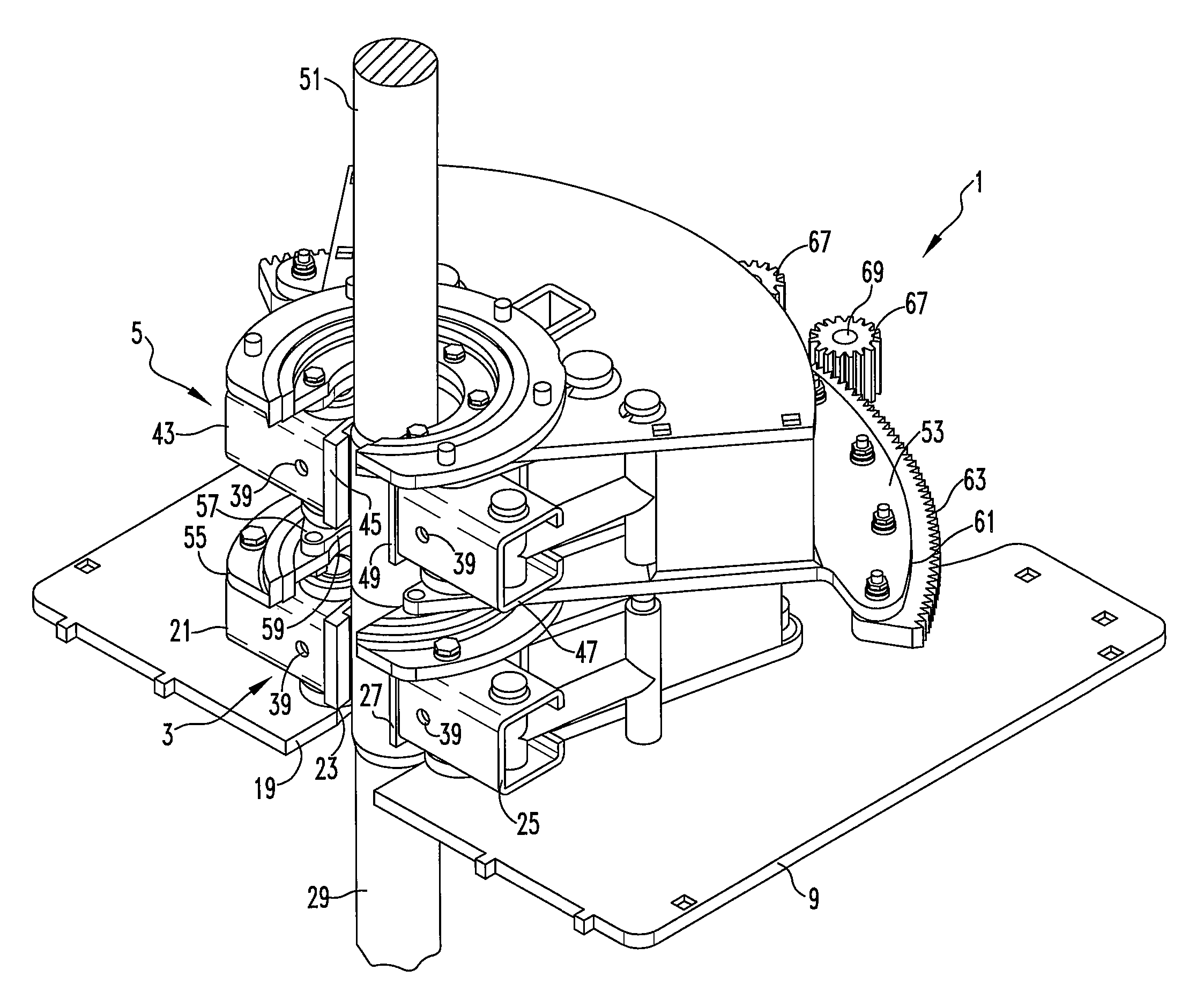
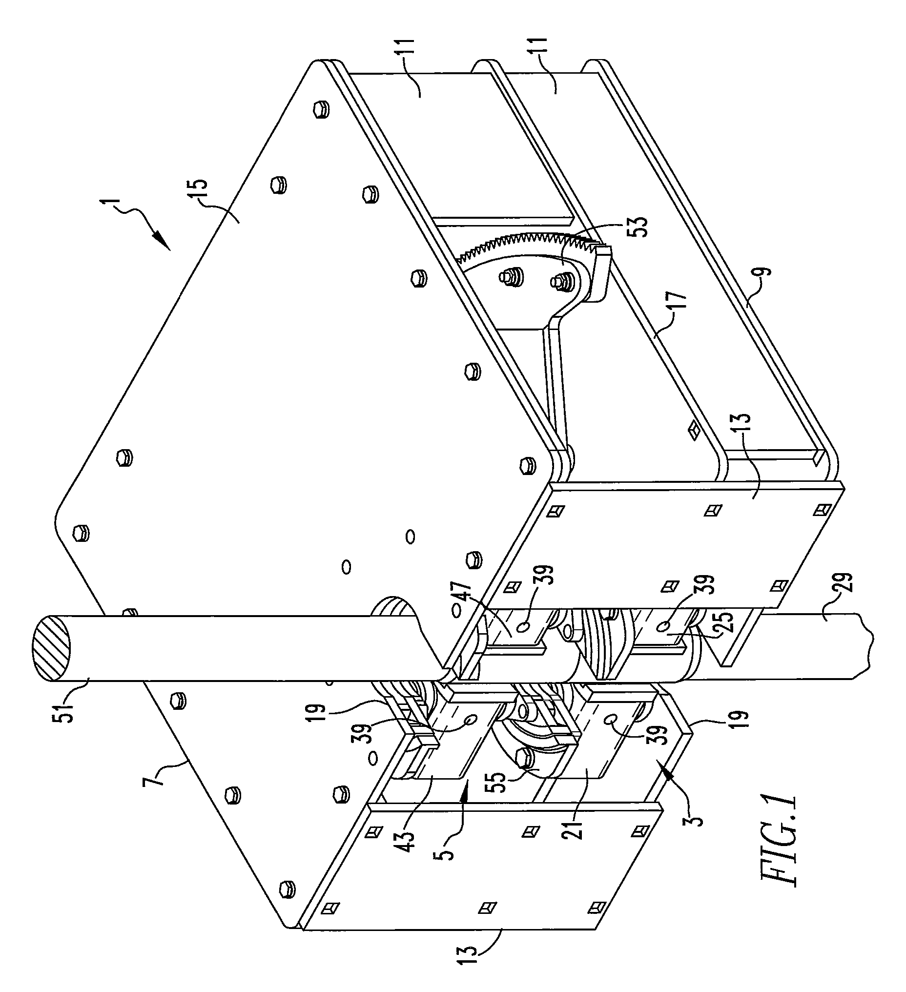
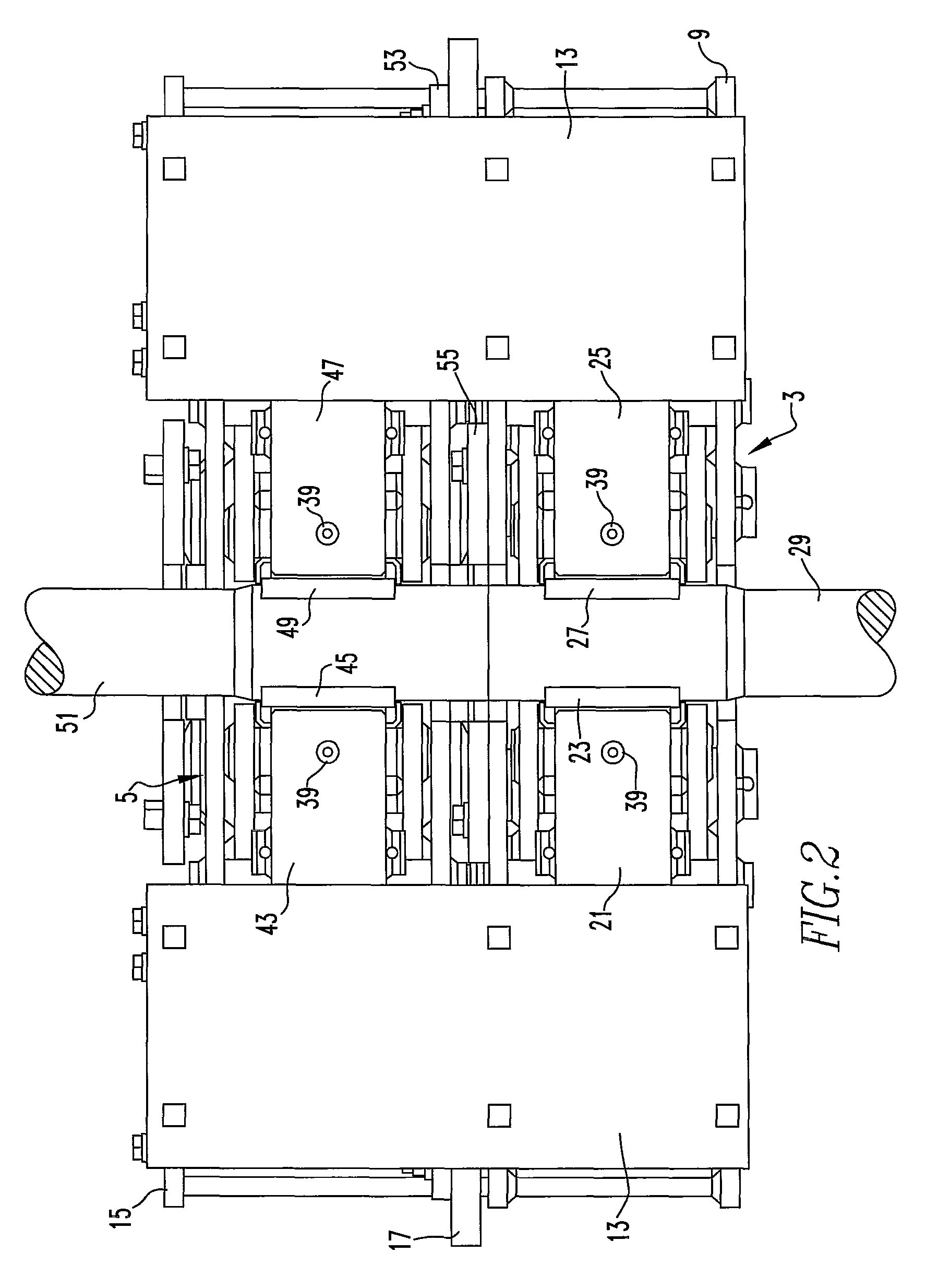
[0030]With reference to FIGS. 1-8, an apparatus for connecting and disconnecting well drilling components, denoted generally as reference numeral 1, such as an Iron Roughneck, includes a first or stationary clamping mechanism, denoted generally as reference nu...


PUM

PropertyMeasurementUnit
cross-sectional shapeaaaaaaaaaa
forceaaaaaaaaaa
torqueaaaaaaaaaa

Abstract

An apparatus includes: a first clamping mechanism having a first hollow portion that includes a first gripping die portion disposed therein and a second hollow portion that includes a second gripping die portion disposed therein such that a first well drilling component is positioned therebetween; a wedge-shaped plate positioned above the first clamping mechanism and including a first end having a notch formed therein and a second arcuate end having gear teeth formed therein; a second clamping mechanism supported by the wedge-shaped plate and including a first hollow portion having a first gripping die portion disposed therein and a second hollow portion having a second gripping die portion disposed therein such that a second well drilling component is positioned therebetween; and a drive mechanism. Operation of the drive mechanism rotates the wedge-shaped plate and the second clamping mechanism through about a 90° range of motion.

Description

CROSS REFERENCE TO RELATED APPLICATIONS[0001]This application claims the benefit of U.S. Patent Application No. 61 / 558,633 entitled “Drill Pipe Breakout Machine” filed Nov. 11, 2011, which is hereby incorporated by reference in its entirety.BACKGROUND OF THE INVENTION[0002]1. Field of the Invention[0003]The present disclosure is generally directed to an apparatus for connecting and disconnecting tubular members and, more particularly, to an apparatus for connecting and disconnecting well drilling components.[0004]2. Description of Related Art[0005]In the oil and gas industry, a drill string is used by a drilling rig to drill a well bore. The drill string is typically composed of drill pipe and a bottom hole assembly. The bottom hole assembly typically includes a drill bit, drill collars, and other drilling related tools. An automated apparatus, commonly known as an “Iron Roughneck”, may be utilized to makeup (i.e., connect) and breakout (i.e., disconnect) threaded joints of drill pi...

Claims


Application Information

Patent Timeline
Patent Type & Authority Patents(United States)
IPC IPC(8): B25B17/00E21B19/16
CPCB25B17/00E21B19/164Y10T29/49826
Inventor BARNETT, RYANCONKLIN, BRODY
Owner TARGET DRILLING
Why Eureka
Try Eureka