Imaging lens

a technology of imaging lens and chromatic aberration, applied in the field of imaging lens, can solve the problems of limiting the angle of even wider angle, the mounting of imaging lens, and the difficulty of achieving both wide angle and downsizing of imaging lens, and achieve the effect of restrainting the generation of chromatic aberration and restricting the chromatic aberration of imaging lens

Active Publication Date: 2015-09-29
TOKYO VISIONARY OPTICS CO LTD
View PDF2 Cites 0 Cited by
  • Summary
  • Abstract
  • Description
  • Claims
  • Application Information

AI Technical Summary

Benefits of technology

[0016]As described above, according to the imaging lens having the three-lens configuration, in which the second lens has negative refractive power, in an attempt to attain both downsizing of the imaging lens and the wide angle, each lens tends to have relatively strong refractive power. Consequently, it is necessary to enhance fabrication accuracy and assembly accuracy of the lens. According to the first aspect of the present invention, since two of the three lenses, which are disposed on the object side, have positive refractive powers, it is possible to have positive refractive power by the two lenses and thereby it is achievable to have refractive power of each lens relatively weak. As such, it is possible to satisfactorily achieve both downsizing and wider angle. Moreover, since refractive power of each lens that composes the imaging lens is relatively weak, he surface shape of each lens can be gentle, and it is achievable to improve workability and assemblability of the imaging lens.
[0022]When the imaging lens satisfies the conditional expression (3), it is achievable to restrain a field curvature, an astigmatism, and a distortion within satisfactory ranges in a well-balanced manner, while restraining the incident angle of a light beam emitted from the imaging lens to the imaging element within the range of the chief ray angle. When the value exceeds the upper limit of “1.0”, although it is easy to restrain the incident angle of a light beam emitted from the imaging lens to the imaging element within the range of the chief ray angle, the astigmatic difference increases, so that it is difficult to obtain satisfactory image-forming performance. On the other hand, when the value is below the lower limit of “0.5”, the distortion increases and the image-forming surface curves to the object side, so that it is difficult to obtain satisfactory image-forming performance. Moreover, it is also difficult to restrain the incident angle of a light beam emitted from the imaging lens to the imaging element within the range of the chief ray angle, and shading easily occurs.
[0028]When the imaging lens satisfies the conditional expressions (6) to (8), the Abbe's number of each lens that composes the imaging lens is large, so that it is possible to restrain generation of chromatic aberrations generated upon passing through each lens, and thereby it is achievable to suitably restrain the chromatic aberration of the imaging lens.

Problems solved by technology

In addition, although the lens configuration is slightly unfavorable in view of downsizing of the imaging lens and satisfactory correction of aberrations, as a lens that has a small F number and is bright, for example, there is known an imaging lens described in Patent Reference 2.
Although the imaging lens described in Patent Reference 1 has the wider angle of view than that of conventional one, there is a limit by itself for attaining even wider angle.
Accordingly, it is difficult to achieve both wider angle and downsizing of the imaging lens.
Rather, it is a common problem also for an imaging lens to be mounted in a relatively small camera such as digital still cameras, security cameras, vehicle onboard cameras, and network cameras.

Method used


Image

  • Imaging lens
  • Imaging lens
  • Imaging lens

Examples


Embodiment Construction

[0044]Hereunder, referring to the accompanying drawings, an embodiment of the present invention will be fully described.

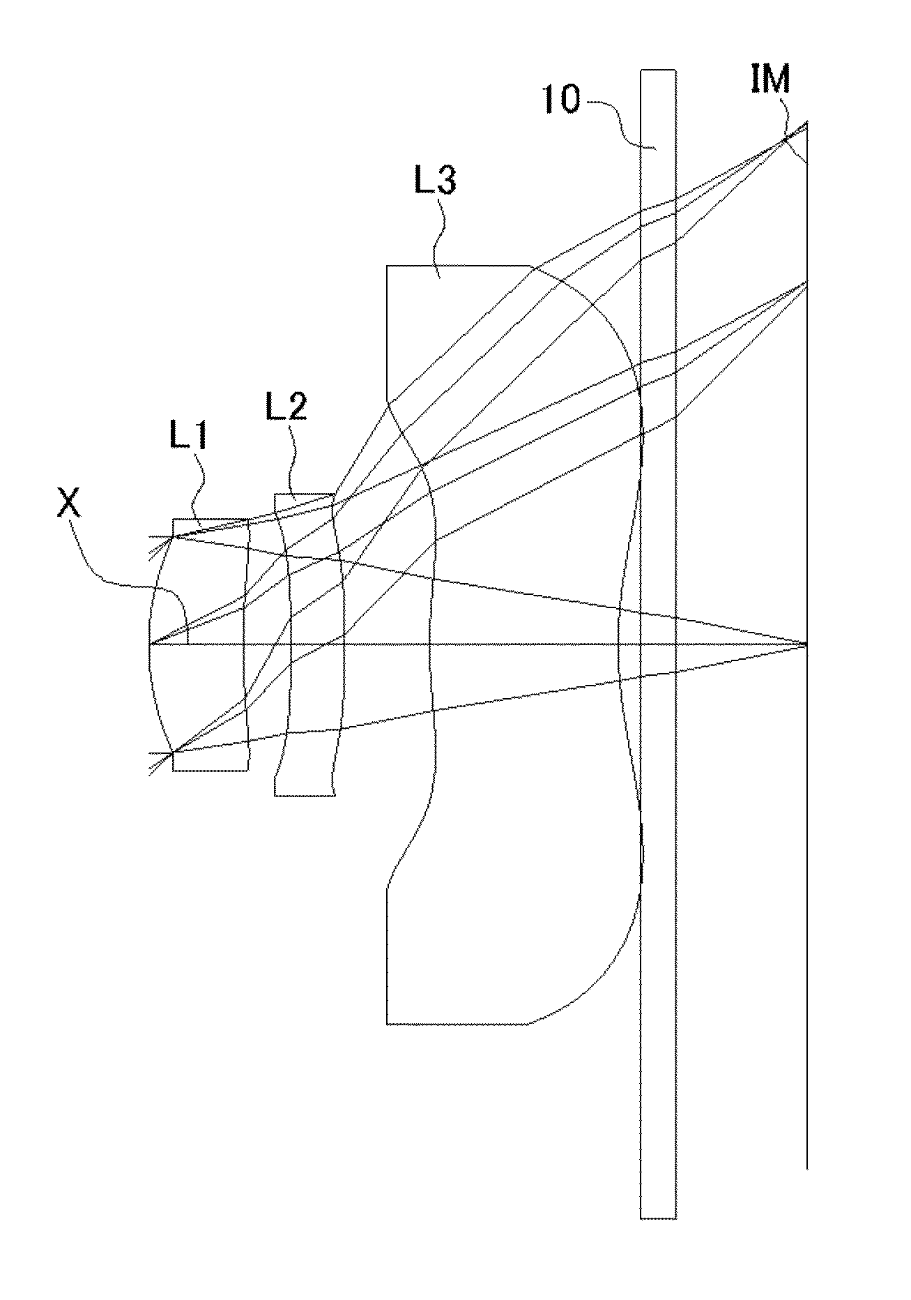
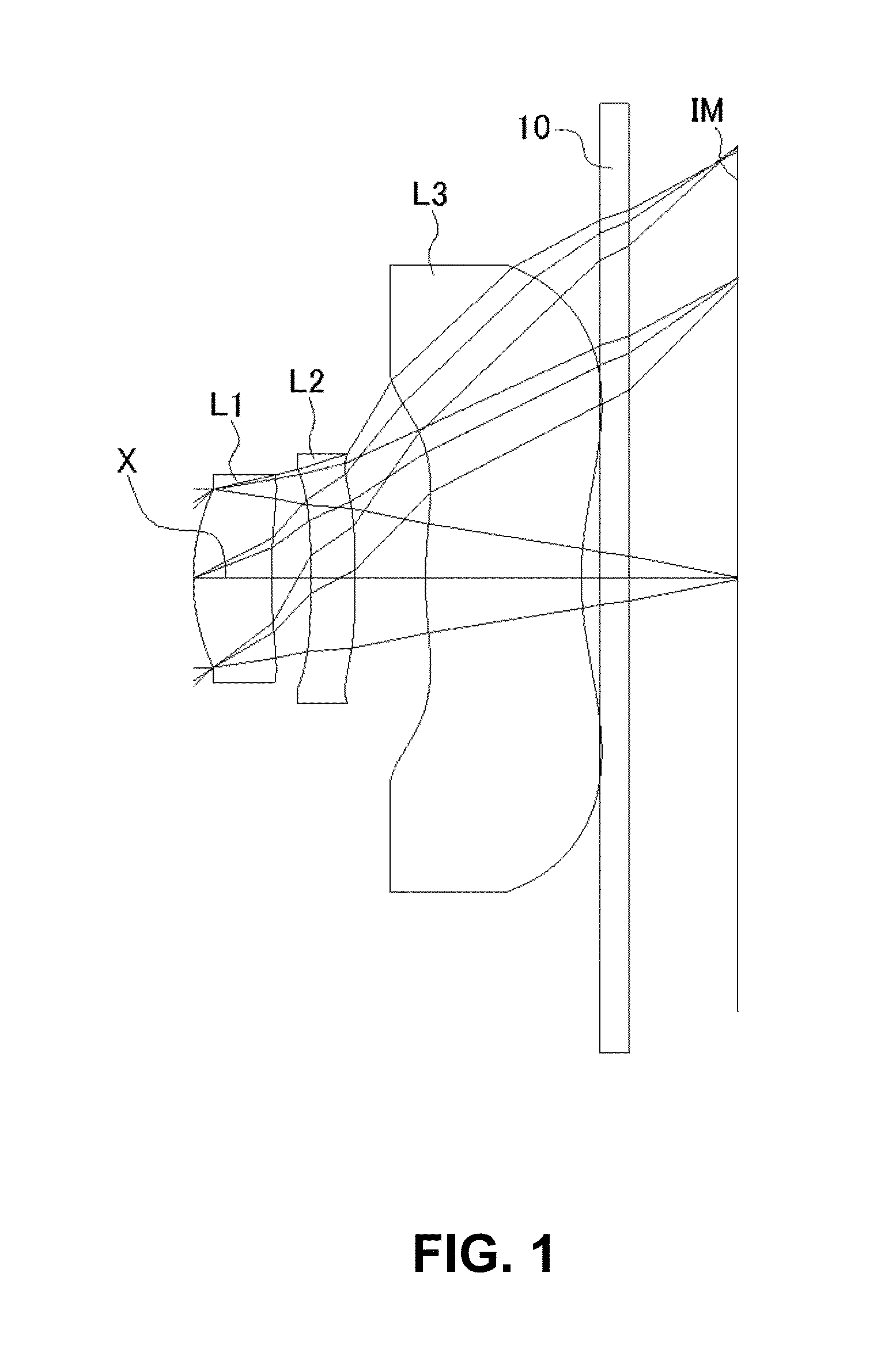
[0045]FIGS. 1, 4, 7, 10, and 13 are schematic sectional views of imaging lenses in Numerical Data Examples 1 to 5 according to the embodiment, respectively. Since a basic lens configuration is the same among those Numerical Data Examples, the lens configuration of the embodiment will be described with reference to the illustrative sectional view of Numerical Data Example 1.

[0046]As shown in FIG. 1, the imaging lens of the embodiment includes a first lens L1 having positive refractive power, a second lens L2 having positive refractive power, and a third lens L3 having negative refractive power, arranged in the order from an object side to an image plane side. A filter 10 may be provided between the third lens L3 and an image plane IM of an imaging element. The filter 10 may be optionally omitted. In the imaging lens of the embodiment, there is provided an aperture s...


PUM


Abstract

An imaging lens includes a first lens having positive refractive power; a second lens having positive refractive power; and a third lens having negative refractive power, arranged in the order from an object side to an image plane side. The first lens and the third lens respectively have an object-side surface and an image plane-side surface whose curvature radii are both positive. The second lens has an image plane-side surface whose a curvature radius is negative. In addition, when the first lens has refractive power P1, the second lens has refractive power P2, the third lens has refractive power P3, the curvature radius of the image plane-side surface of the second lens is R2r, and the curvature radius of the object-side surface of the third lens is R3f, the imaging lens satisfies specific conditional expressions.

Description

BACKGROUND OF THE INVENTION AND RELATED ART STATEMENT[0001]The present invention relates to an imaging lens for forming an image of an object on an imaging element such as a CCD sensor and a CMOS sensor. In particular, the present invention relates to an imaging lens suitable for mounting in a relatively small-sized camera such as a camera for mounting in a portable device, which includes a cellular phone, a smartphone, and a portable information terminal, a digital still camera, a security camera, a vehicle onboard camera, and a network camera.[0002]In these years, in place of cellular phones that are intended mainly for making phone calls, so-called “smartphones” have been more widely used, i.e., cellular phones with functions of portable information terminals (PDA) and / or personal computers. Since the smart phones generally are highly functional and exhibit high performance as opposed to the cellular phones, it is possible to directly edit images taken by a camera thereof without...

Claims


Application Information

Patent Timeline
Patent Type & Authority Patents(United States)
IPC IPC(8): G02B9/16G02B13/00
CPCG02B13/0035
Inventor KUBOTA, YOJIKUBOTA, KENICHIHIRANO, HITOSHIKURIHARA, ICHIROYONEZAWA, TOMOHIRO
Owner TOKYO VISIONARY OPTICS CO LTD
Why Eureka
Try Eureka