Wind energy installation working gantry and wind energy installation

a technology for wind energy installation and working gantry, which is applied in the direction of final product manufacture, machines/engines, transportation and packaging, etc., can solve the problems of serious safety loopholes, and achieve the effect of improving safety against accidents involving falling

Active Publication Date: 2015-10-06
WOBBEN PROPERTIES GMBH
View PDF29 Cites 0 Cited by
  • Summary
  • Abstract
  • Description
  • Claims
  • Application Information

AI Technical Summary

Benefits of technology

[0007]One or more embodiments of the present invention are directed to providing a wind power installation working gallery, a locking device provided for same, a lift and a wind power installation, which respectively may provide improved safety against accidents involving falling.
[0009]The invention is based on the realization that safety to prevent an unintended fall through the transfer region of the railing of the working gallery is most effectively improved by preventing the lift from moving away from the working gallery without previously securing the transfer region by locking the closure element relative to the working gallery. According to one embodiment of the invention, to unlock the locking device of the working gallery, the first locking element is moved into a locking position relative to the locking mechanism of the locking device.
[0010]Due to the fact that the first locking element however is also connected to the lift and in particular is mechanically fixedly connected thereto, in addition to the first locking element, the lift is also in a locking position when the second locking element associated with the closure element on the working gallery is in a release position. According to one embodiment of the invention, the locking position of the first locking element can be released exclusively by the second locking element being moved into a locking position relative to the locking device. Consequently the locking mechanism of the locking device is to be designed to always hold either the first locking element or the second locking element in a locking position so that there are two safety-relevant conditions alternatively. These are on the one hand locking of the closure element on the working gallery in the absence of the lift and secondly the presence of the lift at the working gallery in the release position of the closure element. In this embodiment, the removal of the first locking element and thus release of the lift from the working gallery is prevented when the closure element is not locked on the working gallery.
[0014]Particularly preferably the locking mechanism is designed in the manner of a deposit lock system. The advantage in using a deposit lock system is in particular that such systems are commercially available and can also be retro-fitted at very low cost to older working galleries which are already installed. The term deposit lock system is used to denote for example a lock system for shopping trolleys or baggage storage facilities.
[0015]The locking mechanism is preferably arranged within a housing of the locking device. The housing ensures protection from damage and / or improper opening of the locking mechanism in a manner which is not in accordance with the specified requirements. This also provides protection from the ingress of dirt.
[0016]In a preferred embodiment of the working gallery the locking mechanism in the locking device is arranged stationarily on the working gallery, preferably on the railing. Arranging the locking mechanism at a height which is agreeable to a user, preferably at hip height, simplifies operation.

Problems solved by technology

That is considered as a disadvantage in the state of the art and at the same time is perceived as a serious safety loophole.

Method used


Image

  • Wind energy installation working gantry and wind energy installation
  • Wind energy installation working gantry and wind energy installation
  • Wind energy installation working gantry and wind energy installation

Examples


Embodiment Construction

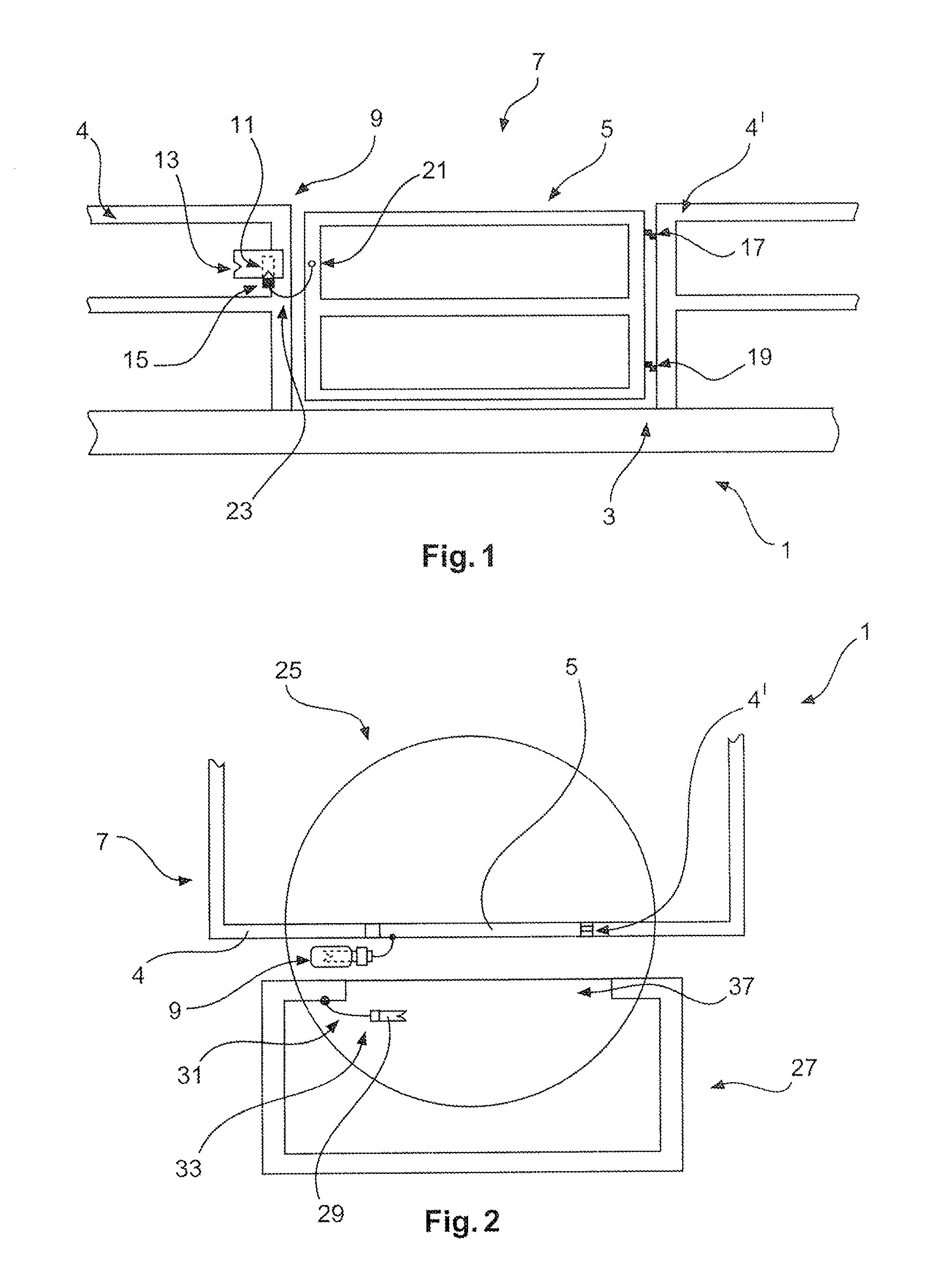
[0034]FIG. 1 shows a transfer region between a lift and a working gallery or platform structure 1 according to the present invention, looking from the direction of the lift. The wind power installation working gallery 1 has a working platform 3 and a railing 7. The railing 7 can be locked by a closure element 5. The closure element is fixed pivotably with a first hinge 17 and a second hinge 19 to a first portion 4′ of the railing 7. A locking device 9 is arranged on a second portion 4 of the railing 7. In the illustrated configuration, the locking device 9 holds a second locking element 15 in a corresponding receiving part. The second locking element 15 is fixed by a second connecting member 23 on a portion 21 opposite the second locking element, on the closure element 5. The second connecting member 23 is in the present case in the form of a chain and the closure element 5 is in the form of a door. The locking device 9 has a receiving part 11 for receiving the second locking elemen...


PUM


Abstract

The present invention concerns a wind power installation working gallery comprising a working platform and a railing arranged on the working platform, wherein the railing can be closed off by means of a closure element and the closure element is arranged in a transfer region to a lift.The invention concerns in particular a wind power installation having a locking device with a locking mechanism for receiving a first locking element and a second locking element, wherein the first locking element is connected to the lift and the second locking element is connected to the closure element, and the locking mechanism is adapted to release one of the two locking elements by means of the locking of the respective other locking element relative to the locking device.The invention further concerns a locking device, a lift and a wind power installation.

Description

BACKGROUND[0001]1. Technical Field[0002]The present invention concerns a wind power installation working gallery comprising a working platform and a railing arranged on the working platform, wherein the railing can be closed off by a closure element and the closure element is arranged in a transfer region to a lift.[0003]The invention further concerns a wind power installation comprising at least one aforementioned wind power installation working gallery, a lift and a locking device for a wind power installation.[0004]2. Description of the Related Art[0005]Working galleries or scaffoldings of the above-indicated kind are used during the erection of wind power installations or for service operations during the working life of wind power installations. Certain types of wind power installations utilize the temporary provision of working galleries on or in a wind power installation, in particular during installation or dismantling, while in other types of installations, in particular la...

Claims


Application Information

Patent Timeline
Patent Type & Authority Patents(United States)
IPC IPC(8): B66B13/16B65G13/12B65G1/08F03D1/00F03D11/00
CPCB66B13/16B65G1/08B65G13/12F03D1/003F03D11/00F05B2230/61Y02E10/72F03D80/00F03D80/50Y02E10/728Y02P70/10Y02P70/50F03D13/20
Inventor MULLER, JOHANN
Owner WOBBEN PROPERTIES GMBH
Why Eureka
Try Eureka