Centric clamping device

a clamping device and centric technology, applied in the field of clamping devices, can solve the problems of inability to achieve the clamping task, inability to achieve centric clamping with a uniform clamping pressure on all clamping jaws, and inability to reliably centric clamp blanks with shape deviations

a clamping device and centric technology, applied in the field of clamping devices, can solve the problems of inability to achieve the clamping task, inability to achieve centric clamping with a uniform clamping pressure on all clamping jaws, and inability to reliably centric clamp blanks with shape deviations

US9156092B2Inactive Publication Date: 2015-10-13KARLEIN BIRGITT

Image

  • Centric clamping device
  • Centric clamping device
  • Centric clamping device

Examples


Embodiment Construction

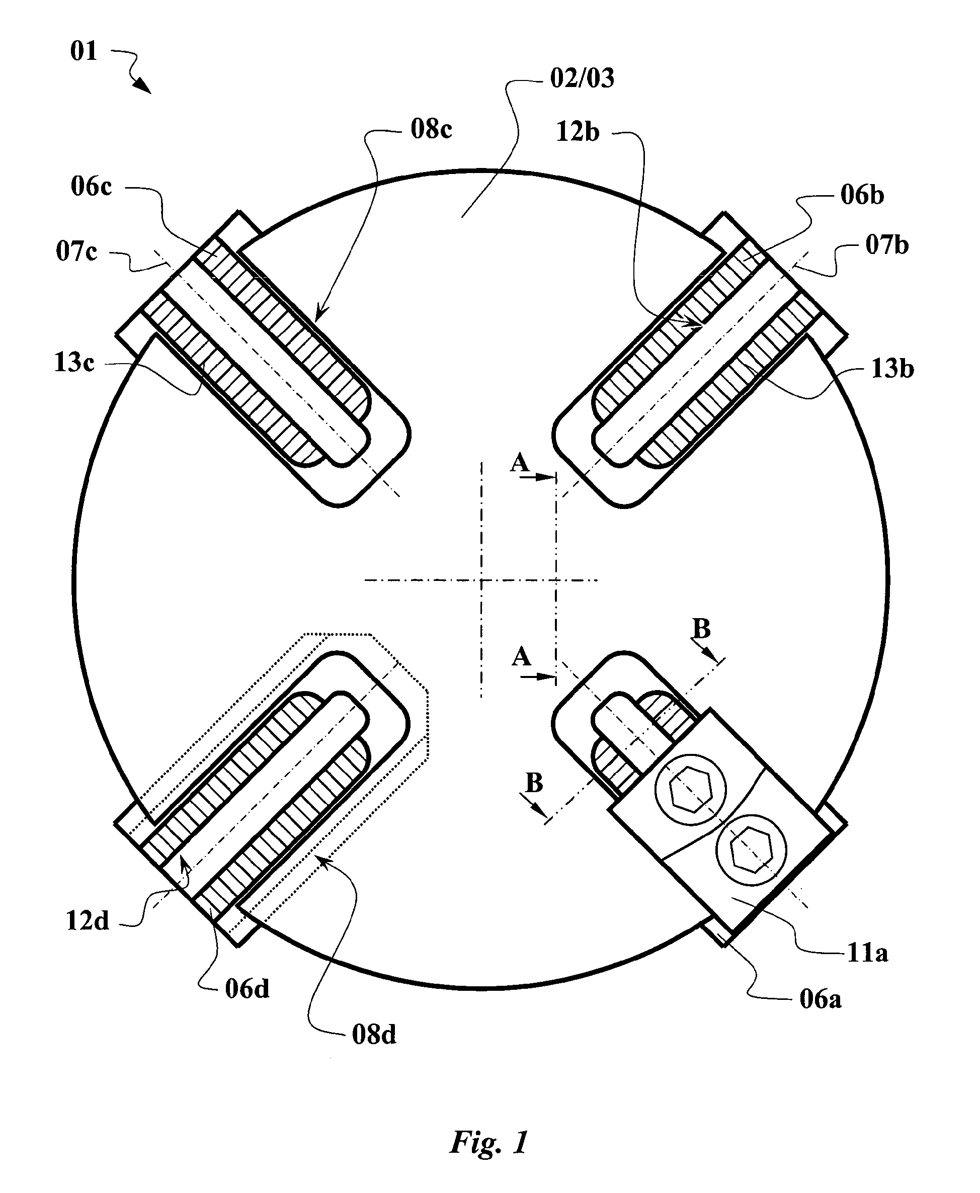
[0075]Referring to the drawings in particular, in FIG. 1, a first embodiment of a clamping device according to the invention 01 is outlined as an example. First of all, it shows the device support 02, respectively the upper housing section 03 of the device support 02 in the circular form. In the device support 02, there are guide grooves in the form of the support guide 08a to 08d. The four basic clamping supports 06a to 06d are inserted into these guide grooves. Along the respective support orientations 07a to 07d, the respective basic clamping supports 06 can be slid in the support guides 08. Furthermore, a clamping jaw 11a on the basic clamping support 06a is outlined as an example. Here, the clamping jaw 11 can be moved along jaw guides 12 in parallel with the support guides 06. In this respect, the clamping jaw 11 can also be displaced radially in relation to the axis of rotation. In order to lock the position of the clamping jaw 11 in relation to the basic clamping support 06,...


PUM


Abstract

A clamping device (01), for use on a lathe, includes a plurality of basic clamping supports (06), which can be moved in a star-shaped formation in relation to an axis of rotation and on each of which a clamping jaw (11) for clamping workpieces can be attached. The basic clamping supports (06) can be adjusted simultaneously by means of an adjusting drive (21, 36) of the clamping device (01). At least two basic clamping supports (06) are coupled directly or indirectly to one another by an outer rocker (15). At least in the middle of the adjusting path, a limited inward displacement of a basic clamping support (06a, 06c, and 06b, 06d, respectively) leads to a swiveling of the outer rocker (15a, 15c) and an outward displacement of the other coupled basic clamping support (06b, 06d, and 06a, 06c, respectively).

Description

CROSS REFERENCE TO RELATED APPLICATIONS[0001]This application is a United States National Phase application of International Application PCT / DE2011 / 000345 and claims the benefit of priority under 35 U.S.C. §119 of German Application DE 10 2010 023 797.3 filed Jun. 15, 2010, the entire contents of which are incorporated herein by reference.FIELD OF THE INVENTION[0002]The invention relates to a clamping device for use with a lathe or the like for clamping workpieces by means of a plurality of clamping jaws.BACKGROUND OF THE INVENTION[0003]Chucks for lathes in different designs are well-known from the state of the art. For clamping round workpieces, the state of the art normally uses a three-jaw chuck with lathes and a so-called four jaw chuck for clamping square workpieces. In this regard there is no need for further elaboration. Normal chucks have in common that the plurality of clamping jaws—normally three or four—are simultaneously adjusted manually, hydraulically or electrically a...

Claims


Application Information

Patent Timeline
13 Oct 2015
Publication
US9156092B2
IPC
B23B31/16; B23B31/02
CPC
B23B31/02; B23B31/16; B23B31/16045; B23B2215/64; B23B2231/22; Y10T279/1961; Y10T82/2572; Y10T82/2579
Inventors
KARLEIN, BIRGITT; KARLEIN, EUGEN