
Indoor fire hydrant and associated method

a fire hydrant and fire hose technology, applied in the field of fire extinguisher equipment, can solve the problems of newer homes and communities, particularly bad seasons, and the worst may be yet to come, and achieve the effects of convenient installation of fire hoses, stable position, and convenient location

Active Publication Date: 2015-10-27
MEADE MELBOURNE SYLVESTER
View PDF14 Cites 25 Cited by
  • Summary
  • Abstract
  • Description
  • Claims
  • Application Information

AI Technical Summary

Benefits of technology

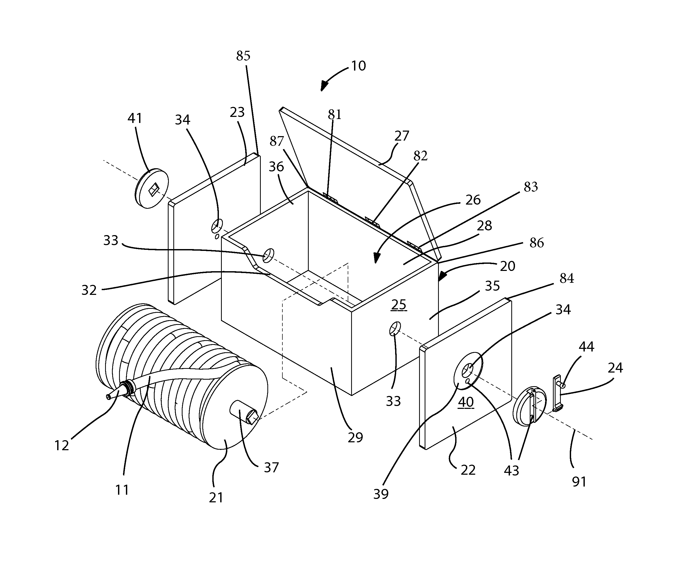
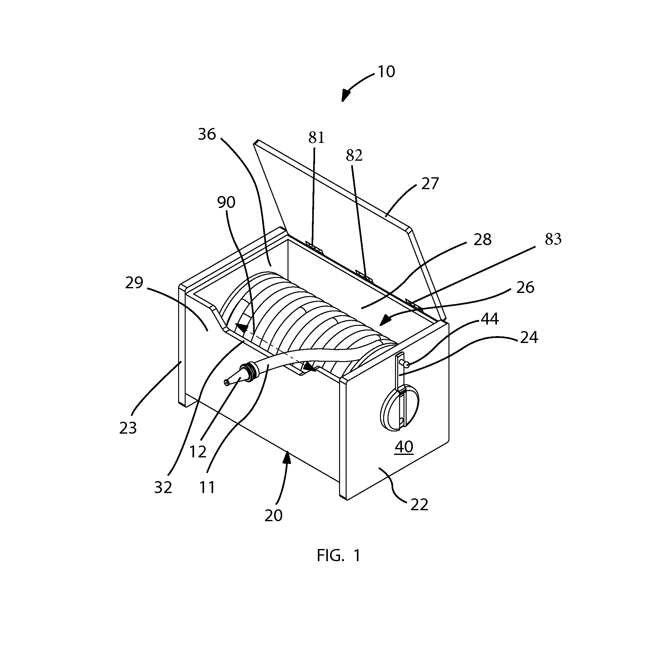
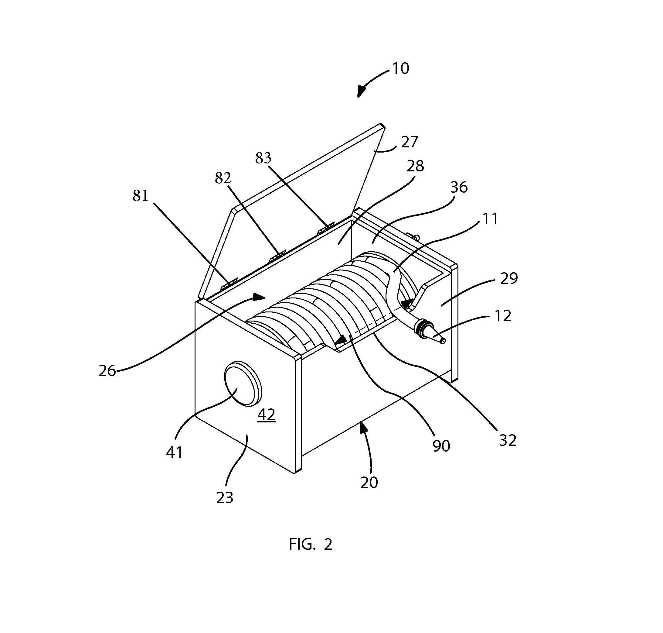
The patent describes an apparatus for winding and unwinding a fire hose in a fireproof casing. The apparatus includes a stabilizing plate attached to the casing, which absorbs and distributes operating forces, keeping the casing stable during operation. The casing is designed to hold a compact reel of fire hose, making it easy to install in a home without taking up too much space. The apparatus also includes a handle with a rotating part that maintains direct contact with the spool, allowing for smooth operation. The apparatus is designed to be easily assembled with minimal parts and ensures that the fire hose is not accidentally uncoiled when stowed in the casing.

Problems solved by technology

The patent text discusses the problem of fire outbreaks and their impact on insurers and the insurance industry. The text highlights the need for a device or apparatus that can protect homes and structures from brush fires or forest fires. The present invention is an indoor fire hydrant that is easy to use, durable, and versatile in applications. The technical problem addressed by the invention is the lack of a convenient and effective means to fight fire outbreaks in and around the house.

Method used


Image

  • Indoor fire hydrant and associated method
  • Indoor fire hydrant and associated method
  • Indoor fire hydrant and associated method

Examples


Embodiment Construction

[0028]The present invention will now be described more fully hereinafter with reference to the accompanying drawings, in which a preferred embodiment of the invention is shown. This invention may, however, be embodied in many different forms and should not be construed as limited to the embodiment set forth herein. Rather, this embodiment is provided so that this application will be thorough and complete, and will fully convey the true scope of the invention to those skilled in the art. Like numbers refer to like elements throughout the figures.

[0029]The illustrations of the embodiments described herein are intended to provide a general understanding of the structure of the various embodiments. The illustrations are not intended to serve as a complete description of all of the elements and features of apparatus and systems that utilize the structures or methods described herein. Many other embodiments may be apparent to those of skill in the art upon reviewing the disclosure. Other ...


PUM


Abstract

An indoor retractable fire extinguishing apparatus may include a portable fireproof casing adapted to be positioned inside the building structure. A spool may be rotatably situated inside the fireproof casing. A fire hose may be rolled up about the spool. A plurality of stabilizing plates may be statically mounted to the fireproof casing. A handle may be attached to the spool in such a manner that the handle and the spool may rotate in sync and thereby cause the fire hose to wind and unwind from the spool respectively while the stabilizing plates remain stationary exterior of the fireproof casing. The stabilizing plates may further be directly attached to an outer surface of the fireproof casing such that operating forces acting on the handle and the spool are absorbed and distributed along the stabilizing plates thereby maintaining the fireproof casing at a substantially stable position during winding and unwinding operations.

Description


Claims


Application Information

Patent Timeline
Owner MEADE MELBOURNE SYLVESTER
Learn More