Dynamic load reduction system

a load reduction and dynamic technology, applied in the direction of machines/engines, couplings, liquid fuel engines, etc., can solve the problems of fan blade loss, fan blade loss, fan blade loss, etc., and achieve the effect of large rotor imbalan

Active Publication Date: 2015-10-27
GENERAL ELECTRIC CO
View PDF38 Cites 20 Cited by
  • Summary
  • Abstract
  • Description
  • Claims
  • Application Information

AI Technical Summary

Problems solved by technology

Large radial, tangential, or axial loads with respect to an axial centerline of the bolted joint can impose bending moments or tensile forces in the flange that can cause deformation or rupture of the bolts.
During gas turbine engine operation, a foreign body, such as a bird, could impact the fan assembly and cause part or all of a fan blade to become detached from the rotor disk.
Fan blade loss creates a large rotor imbalance, particularly, in early revolutions of the imbalance causing event.
This results in the transmission of potentially damaging imbalance forces to the bolted connection, possibly resulting in the misalignment of the flanges and bearing which they help support.
This could be a particular problem in gas turbine engines and, more so, in aircraft gas turbine engines that use bolted connections to support bearings which, in turn, support rotatable rotors.
Rotor blade failures, which can be caused by foreign objects that are drawn into the fan or compressor, can cause rotor unbalance conditions.
Such rotor unbalance conditions can impose radial, circumferential, and possibly also axial loads sufficient to fail supporting structure causing loss of centerline.
Such rotor unbalance conditions can cause unintended high shear, bending, or tensile loads, or a combination of such loads, applied to the flange connecting bolts, leading to structural damage, bolt deformation, and possibly to bolt rupture and separation of the bolted casings from each other.
This can cause the centerline of the flange of the bearing casing to shift.
This, in turn, can shift the radial location of the bearings which is an undesirable condition even with the engine shutoff and windmilling.

Method used


Image

  • Dynamic load reduction system
  • Dynamic load reduction system
  • Dynamic load reduction system

Examples


Embodiment Construction

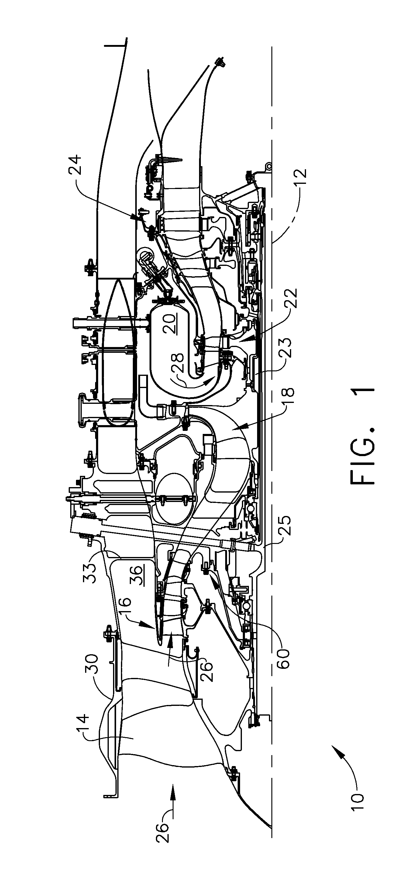
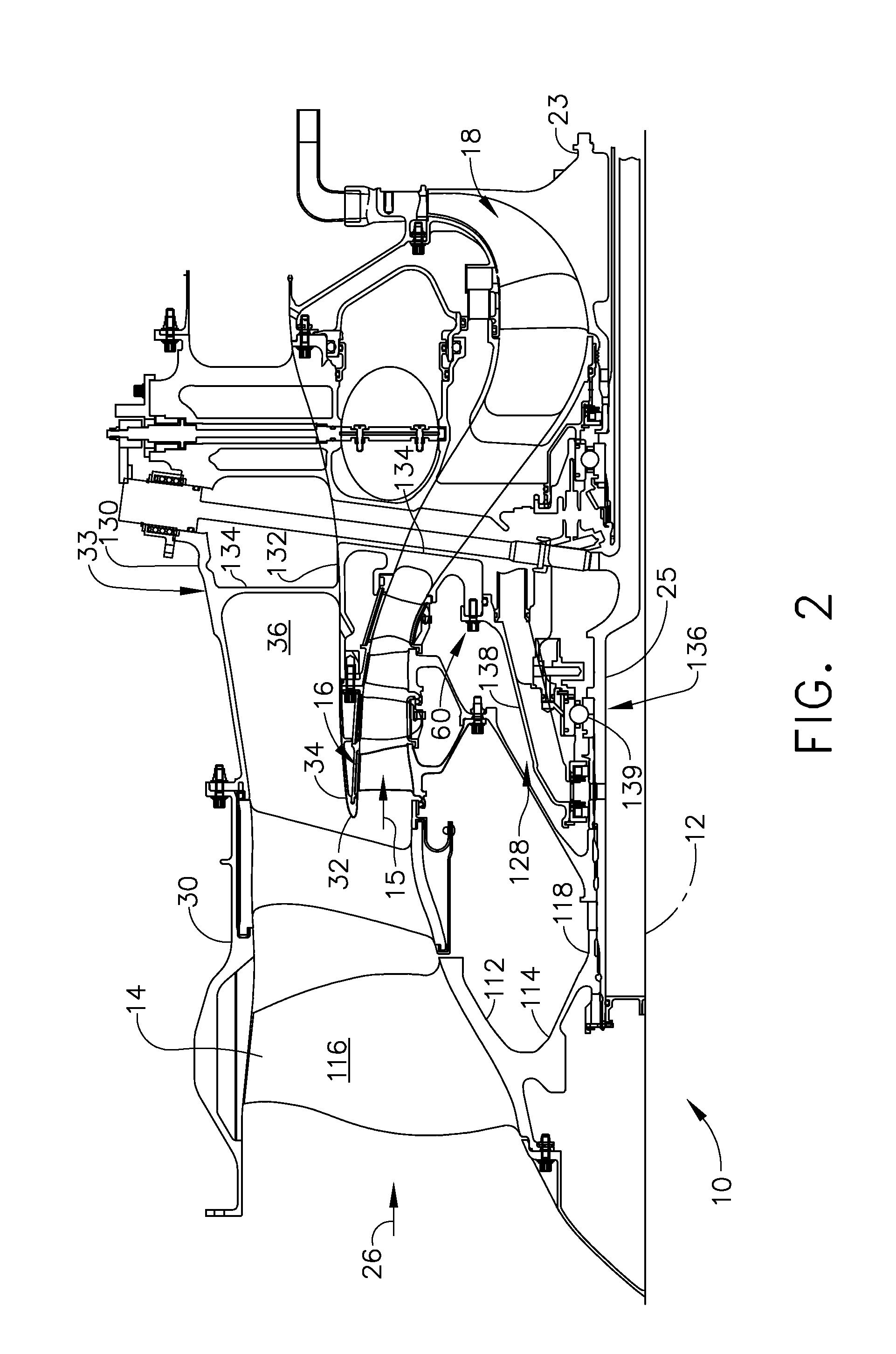
[0022]Illustrated in FIGS. 1 and 2 is an exemplary aircraft turbofan gas turbine engine 10 circumscribed about an engine centerline axis 12 and suitably designed to be mounted to a wing or fuselage of an aircraft. The engine 10 includes, in downstream serial flow communication, a fan 14, a low pressure compressor or booster 16, a high pressure compressor 18, a combustor 20, a high pressure turbine (HPT) 22, and a low pressure turbine (LPT) 24. The HPT or high pressure turbine 22 is joined by a high pressure drive shaft 23 to the high pressure compressor 18. The LPT or low pressure turbine 24 is joined by a low pressure drive shaft 25 to both the fan 14 and the booster 16.

[0023]In typical operation, air 26 is pressurized by the fan 14 and produces an inner air flow 15 channeled through the booster 16 which further pressurizes the inner air flow 15. The pressurized air is then flowed to the high pressure compressor 18 which further pressurizes the air. The pressurized air is mixed wit...


PUM


Abstract

Bolted together first and second flanges include bolts disposed through first bolt holes in the first flange. The bolts extend at least partially through second holes in the second flange. Bolt include bolt heads, threads, and shanks therebetween. Crushable spacers disposed around the shanks of a first plurality of the bolts and contacting and axially extending between the bolt heads and the first flange. Bushings disposed around a second plurality of the bolts and contacting and axially extending between the bolt heads and the second flange. A shank outer diameter may be smaller than a thread diameter and heat shrink tubing may be disposed around the bolt shanks of at least some of the spacers. First bolt holes may extend into an open annular slot on first flange and second holes may extend partially through a forward extending annular rail of second flange with rail received within slot.

Description

BACKGROUND OF THE INVENTION[0001]1. Field of the Invention[0002]The invention relates to bolted flange connections and, particularly, to such connections for limiting transmitted loads during unbalance events in turbomachinery.[0003]2. Description of Related Art[0004]Flanges are generally held together by bolts through bolt holes provided in each of the flanges and that are aligned with each other. Large radial, tangential, or axial loads with respect to an axial centerline of the bolted joint can impose bending moments or tensile forces in the flange that can cause deformation or rupture of the bolts.[0005]During gas turbine engine operation, a foreign body, such as a bird, could impact the fan assembly and cause part or all of a fan blade to become detached from the rotor disk. Such blade loss is a certification requirement under FAA 14 CFR part 33 rules. Fan blade loss creates a large rotor imbalance, particularly, in early revolutions of the imbalance causing event. This results...

Claims


Application Information

Patent Timeline
Patent Type & Authority Patents(United States)
IPC IPC(8): F01D21/04F01D5/02F01D25/04
CPCF01D5/026F01D21/04F01D21/045F01D25/04F05D2260/31Y10T403/645F16B2200/506
Inventor WALLACE, THOMAS TRACYSIMPSON, WILLIAM JOSEPHLIST, JOHN HOWARDTAO, JASON JIANXINSTEEN, TOD ROBERT
Owner GENERAL ELECTRIC CO
Why Eureka
Try Eureka