Extension table with multiple legs

a technology of extension table and supporting legs, which is applied in the field of extension table with multiple legs, can solve the problems of system problems, collapse or cracking of the table or parts of the table, and the risk of the table not being stable when assembled, and achieve the effect of good stability of the supporting legs

Active Publication Date: 2015-11-03
SKOVBY MOEBELFAB
View PDF12 Cites 4 Cited by
  • Summary
  • Abstract
  • Description
  • Claims
  • Application Information

AI Technical Summary

Benefits of technology

[0011]By this construction, in which a transverse rail is used, it is ensured that the first two table legs may be synchronically slid, each keeping their mutual position. This is also a simple way of sliding the table legs.
[0025]This is a preferred embodiment of the sliding means, as the oval shape ensures that the sliding of the mounting is precise and in the direction of the extension. However, depending on the lateral shape of the oval bore, it may also be possible to slide the mounting sideways. In the longitudinal direction, there are good possibilities for sliding and depending on the length of the bores, the position of the first legs may be adjusted in order to release the tension.
[0027]This is a preferred dimension of the bores allowing sufficient adjustment of the table legs.
[0035]Thereby, a good stability of the supporting legs is achieved when the sliding table tops are in a first position as the tops support each other.
[0037]Thereby, a good stability of the supporting legs is achieved in a simple manner when the sliding table tops are in a first position.

Problems solved by technology

However, when the table is made of a living material like wood, the system is problematic.
Naturally, this creates tension in the table and may result in the collapse or cracking of the table or parts of the table.
Additionally, there is a risk of the table not being stable when assembled when a supporting leg leans compared to the leg with which it belongs.
Consequently, the two concurrent legs may not be as supporting and stabilising as they would otherwise be when assembled.
Furthermore, there is a risk of the table being unstable when the legs are separated, whereby the legs wobble, especially when the ground is uneven.

Method used


Image

  • Extension table with multiple legs
  • Extension table with multiple legs
  • Extension table with multiple legs

Examples


Embodiment Construction

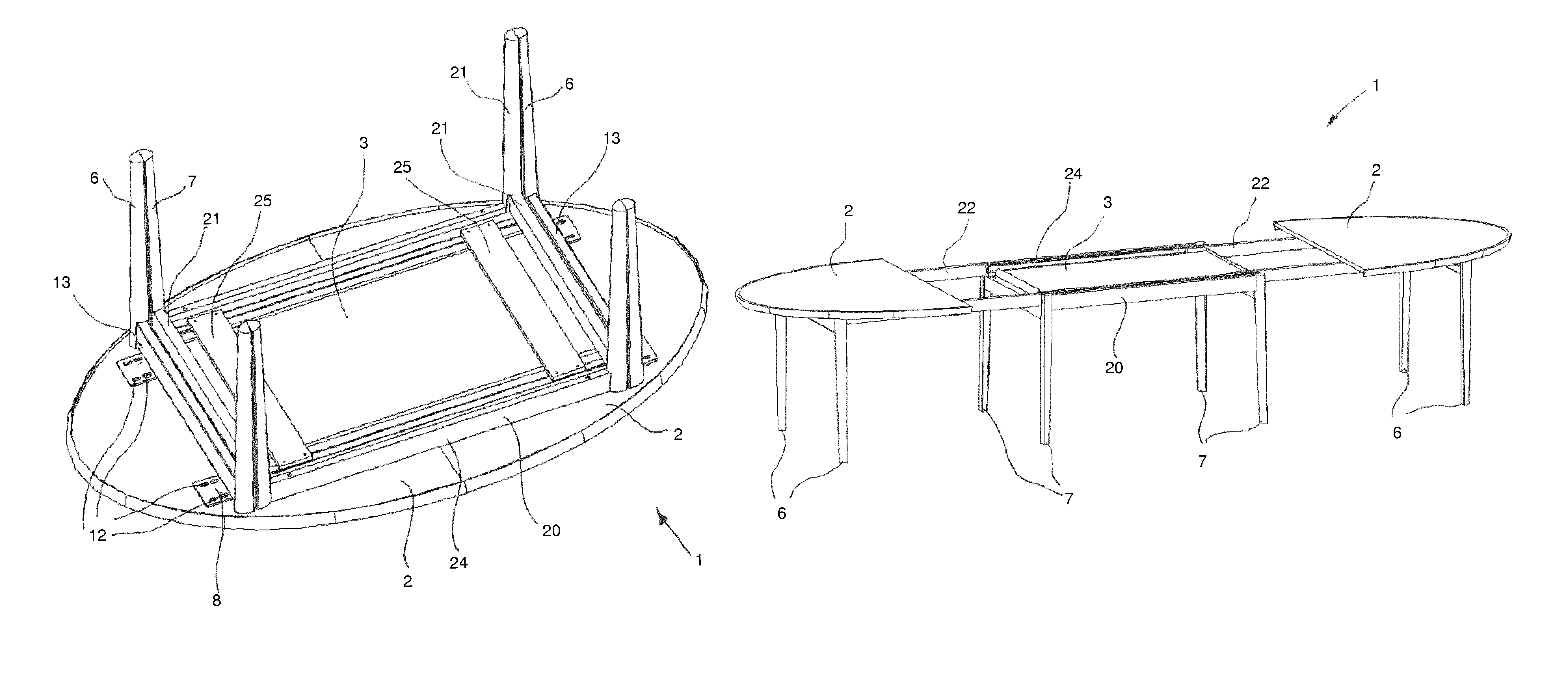
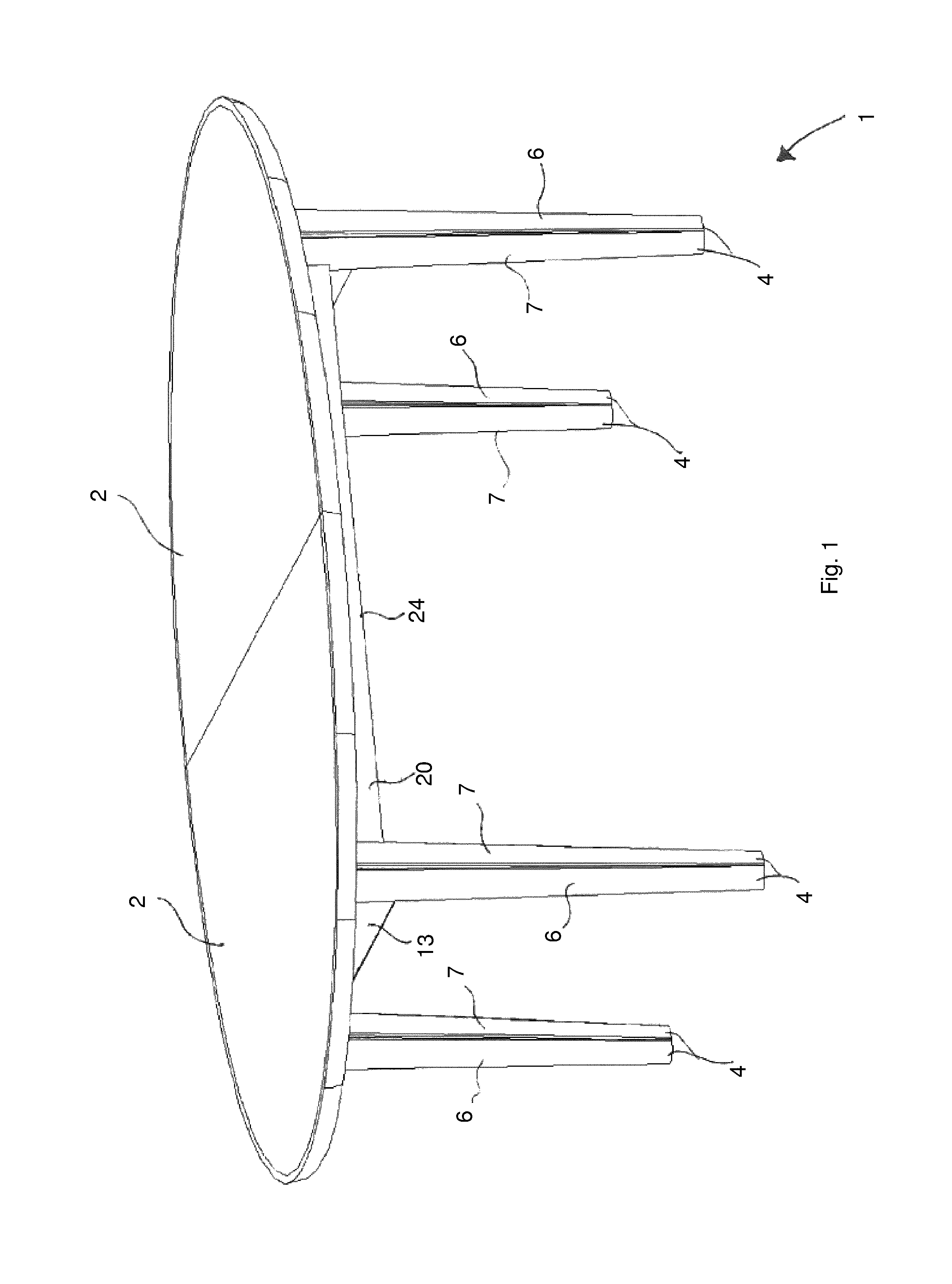
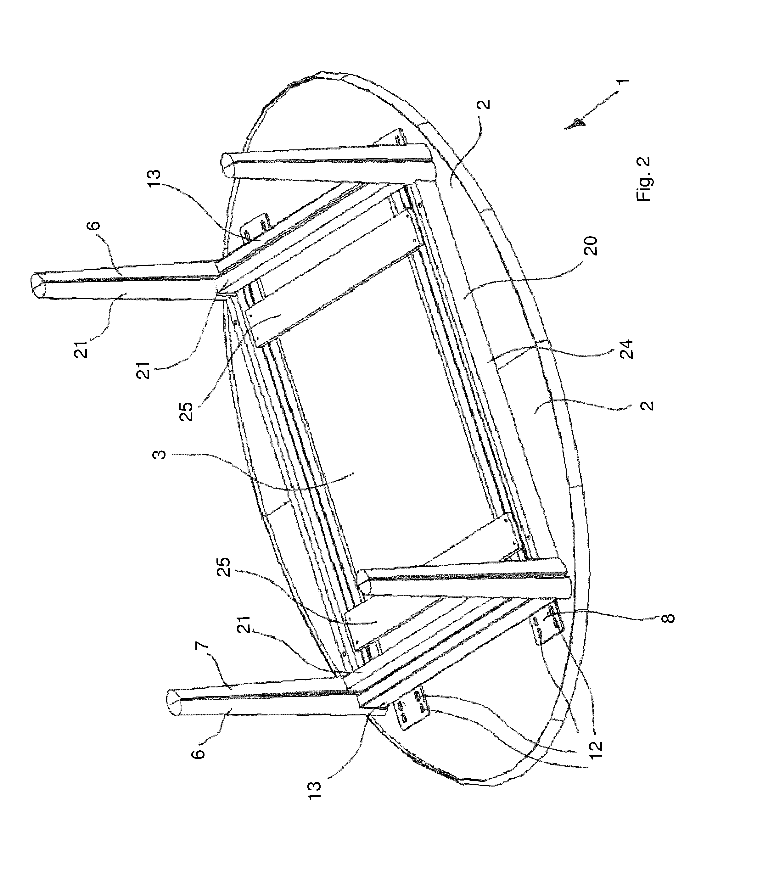
[0045]FIG. 1 shows an extension table with multiple legs 1 according to the invention comprising two sliding table tops 2 being supported by four supporting members 4. A supporting member 4 comprises a first table leg 6 and a second table leg 7. Said two table legs are placed as close to each other as possible when the table 1 is not extended, i.e. in its first position. Typically, the supporting members 4 are oval when seen in cross-sectional view, the longitudinal axis being parallel with the direction of extension of the extension table with multiple legs. The first table leg 6 and the second table leg 7 are half of an oval when seen in a cross-sectional view, and the flat sides of the legs abut each other in the first position. Essentially, the two surfaces abutting each other completely or partially are congruent and thereby, the two surfaces cover each other. In the shown embodiment, the two surfaces are plane. However, the surfaces may bend so that one surface is convex and t...


PUM


Abstract

An extension table with multiple legs with two table tops sliding back and forth in relation to each other and at least one leaf and at least four supporting members each comprising at least two table legs, including a first table leg and a second table leg. The supporting members support the extension table when the sliding table tops are joined in a first position, and they support the extension table when the sliding table tops are pulled apart in a second position. The first table legs in each supporting member are directly or indirectly connected to the sliding table tops through fasteners which, in one embodiment, comprise sliding means.

Description

CROSS REFERENCE TO RELATED APPLICATION[0001]This application is a national stage application pursuant to 35 U.S.C. §371 of International Application No. PCT / EP2013 / 050249, filed Jan. 9, 2013, which claims priority to, and the benefit of, Danish Patent Application No. BA 2012 00005, filed on Jan. 10, 2012, now Danish Patent No. BR 2012 00005, issued on Apr. 29, 2013, the entire contents of which are hereby incorporated herein by reference.TECHNICAL FIELD[0002]The invention relates to an extension table with multiple legs with two sliding table tops sliding back and forth in relation to each other and a number of leaves and at least four supporting members each comprising at least two table legs—a first table leg and a second table leg—said supporting members supporting the extension table with multiple legs when the sliding table tops are joined in a first position and supporting the extension table when the sliding table tops are pulled apart in a second positionBACKGROUND[0003]U.S....

Claims


Application Information

Patent Timeline
Patent Type & Authority Patents(United States)
IPC IPC(8): A47B1/08A47B13/02A47B1/02A47B1/05
CPCA47B1/02A47B1/05A47B13/021A47B2200/005
Inventor HAANSB.AE BUTTED.K, PERRASMUSSEN, PREBEN
Owner SKOVBY MOEBELFAB
Why Eureka
Try Eureka