Cord organizer for portable electronic devices

a technology for organizing and portable electronic devices, applied in the field of organizers, can solve the problems of device being charged to the floor, no protection from fire or electric shock, and users of portable electronic typically struggle with the management of power supply cords, and achieve the effects of convenient storage of power supply cords

Active Publication Date: 2015-11-17
ALEXANDRE CLARK J
View PDF26 Cites 18 Cited by
  • Summary
  • Abstract
  • Description
  • Claims
  • Application Information

AI Technical Summary

Benefits of technology

[0016]An advantage of the invention is in the provision of a solution to neatly and compactly store power cords for portable electronic devices.
[0017]Another advantage of the invention is in the provision of a solution to neatly and compactly store the power supply end for portable electronic devices.
[0018]Another object of the invention is to provide a compact device to improve ease of storage and use of power supply cords for portable electronic devices.
[0019]Yet another object of the invention is to provide convenient storage of power supply cords while allowing variable lengths to be deployed as desired.
[0020]Another object of the invention is in the provision of a compact device and related manual method to store and use power supply cords without the use of springs or any other mechanical elements, other than the rotatable spool.
[0021]Still another object of the invention is in the provision of a device that is not spring loaded, thus it does not have any mechanism that will break down.

Problems solved by technology

A Class 1 circuit is connected to a power limited source but offers no protection from fire or electric shock.
Users of portable electronic typically struggle with cord management of the power supply cord.
The cords are generally over 2 feet long and typically get tangled up with other cords or worse get snagged causing the device being charged to fall to the floor.

Method used


Image

  • Cord organizer for portable electronic devices
  • Cord organizer for portable electronic devices
  • Cord organizer for portable electronic devices

Examples


Embodiment Construction

[0049]In accordance with the present invention a device that stores and organizes a power supply cord for portable electronic devices is provided.

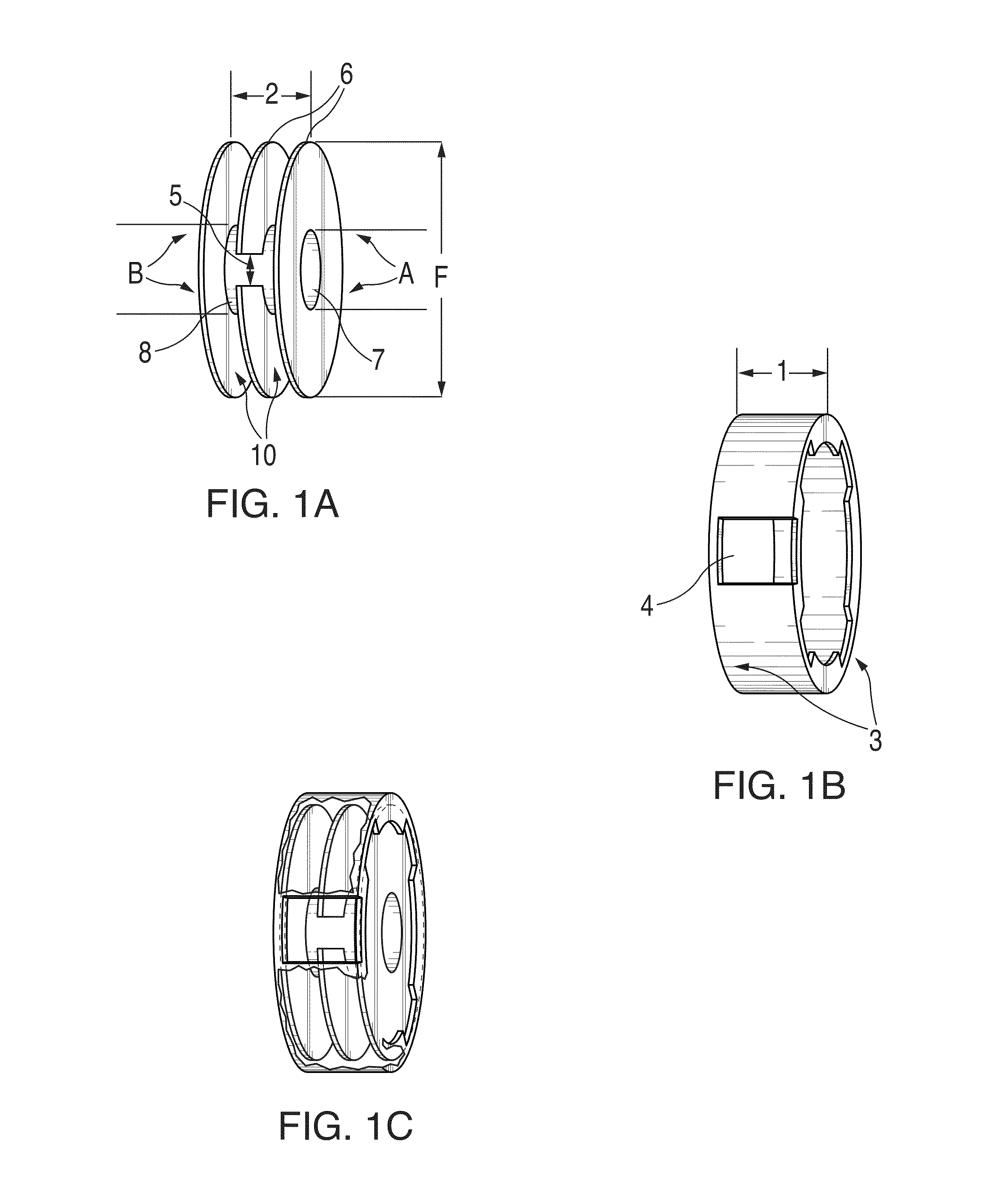
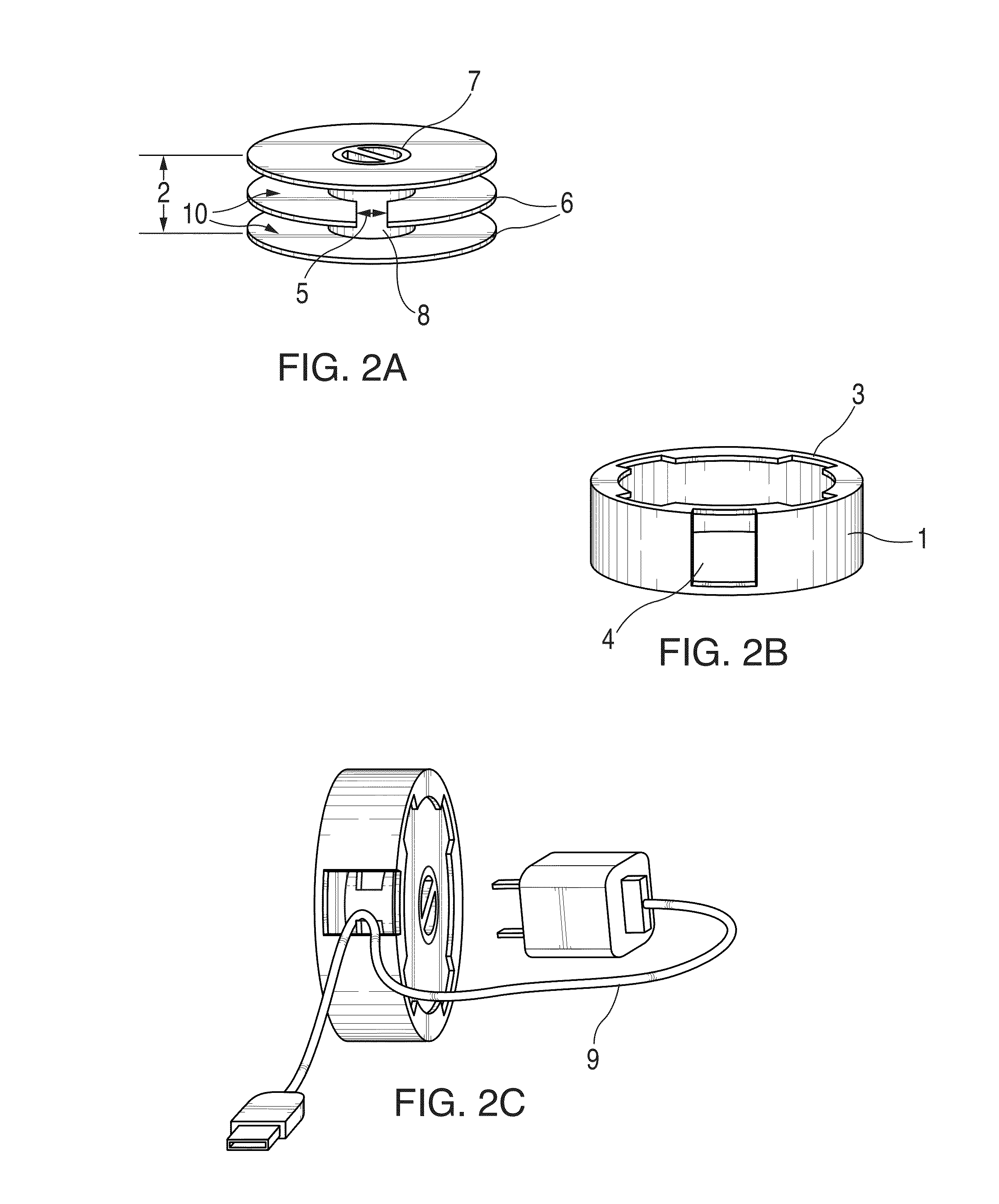
[0050]As described in the accompanying drawings the structures of the invention device are labeled as follows:[0051]1—Outer shell[0052]2—Spool[0053]3—Tread[0054]4—First entry hole[0055]5—Second entry hole[0056]6—Flange[0057]7—Arbor[0058]8—Barrel[0059]9—Power Cord[0060]10—Track

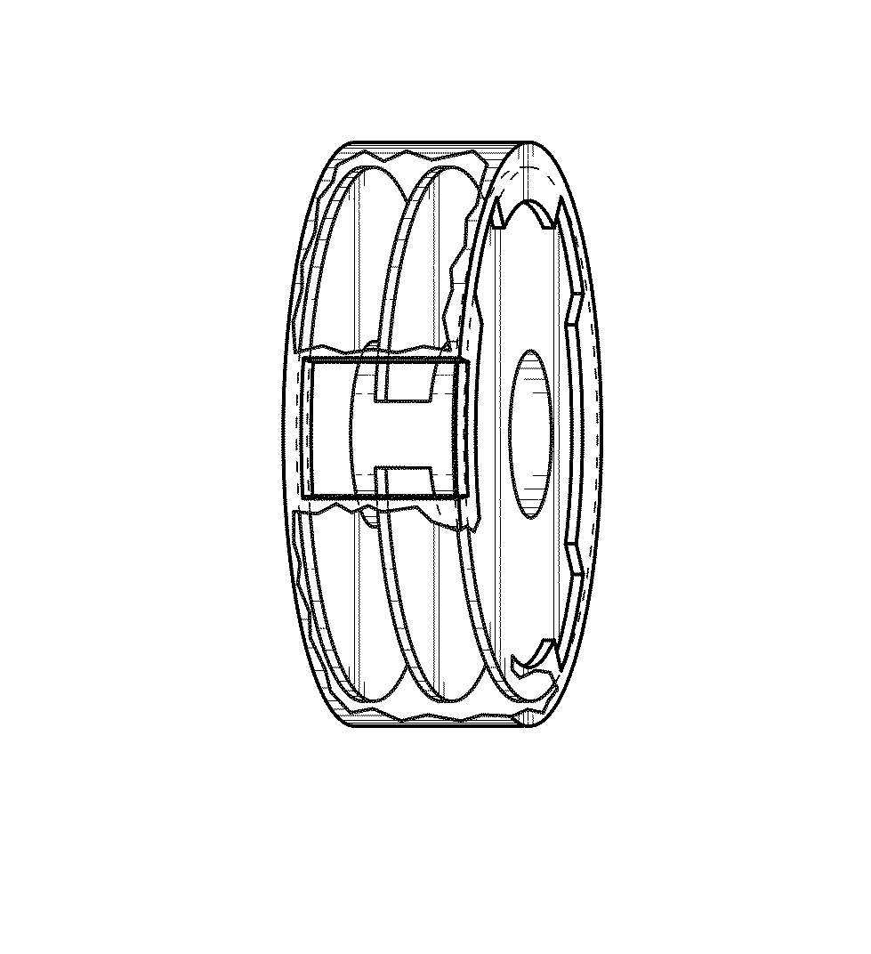
[0061]In general, FIG. 1 is an illustration of a side profile of the components of the invention device in the embodiment with three flanges. FIG. 1A illustrates a side profile of the spool 10, FIG. 1B is a side profile of the shell 1 and FIG. 1C is the spool 2 and shell 1 combined. The spool fits snuggly into the outer shell such that the spool stays in place but can still rotate therein.

[0062]The outer shell 1 has a first entry hole 4 and an inner spool 2 having three circular flanges 6. The flanges are all of equal size and are also referred to herein as right, lef...


PUM


Abstract

A device, and related method, for storing and organizing a power supply cord for portable electronic devices, wherein the device includes an outer shell 1 having a first entry hole 4; and an inner spool 2 having at least two circular flanges 6 connected in the middle by a barrel 8; a track 10 between the flanges; an arbor 7 on the top side and bottom side of the barrel; a second entry hole 5 within the device; and at least one tread 3 on the inner portion of the outer shell, wherein the spool fits snuggly into the outer shell to allow the spool to rotate therein.

Description

[0001]This application claims the benefit of U.S. provisional application No. 61 / 648,656 filed May 18, 2012, which is incorporated herein in its entirety by reference.FIELD OF THE INVENTION[0002]The present invention relates to a cord organizer. In particular the invention relates to device that stores and organizes power supply cords for portable electronic devices.BACKGROUND OF THE INVENTION[0003]The National Electric Code (NEC) provides a classification system for power supplies. The following are relevant to the present invention.[0004]Class 2. A Class 2 circuit is the portion of the wiring system between the load side of a Class 2 power source and the connected equipment.[0005]Class II (with Roman numerals). A Class II circuit refers to power supplies with either a double or reinforced insulation barrier between the input and the output.[0006]Due to its power limitations, a Class 2 or Class II circuit considers safety from a fire initiation standpoint and provides acceptable pr...

Claims


Application Information

Patent Timeline
Patent Type & Authority Patents(United States)
IPC IPC(8): B65H75/34B65H75/14B65H75/44B65H75/40B65H75/28
CPCB65H75/34B65H75/146B65H75/28B65H75/406B65H75/4471B65H2701/34
Inventor ALEXANDRE, CLARK J.
Owner ALEXANDRE CLARK J
Why Eureka
Try Eureka