Supercharge Your Innovation With Domain-Expert AI Agents!

Adjusting device for coin counting machine

a coin counting machine and adjusting device technology, applied in coin/paper handlers, coin counters, instruments, etc., can solve problems such as troublesome operation and complicated structure, and achieve the effect of adjusting the bounce distance of coins

Active Publication Date: 2015-11-17
CHEN CHIU MING
View PDF3 Cites 1 Cited by
  • Summary
  • Abstract
  • Description
  • Claims
  • Application Information

AI Technical Summary

Benefits of technology

[0005]The primary object of the present invention is to provide an adjusting device for a coin counting machine which is capable of adjusting a bounce distance of coins with user's one hand easily.

Problems solved by technology

However, such a conventional adjusting device is complicated and has to be operated by user's two hands, thus having complicated structure and troublesome operation.

Method used


Image

  • Adjusting device for coin counting machine
  • Adjusting device for coin counting machine
  • Adjusting device for coin counting machine

Examples


Embodiment Construction

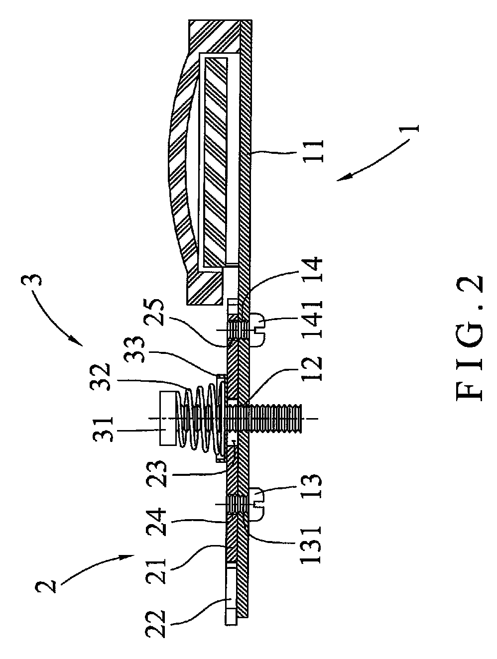
[0015]With reference to FIGS. 1 and 2, an adjusting device for a coin counting machine according to a first embodiment of the present invention comprises: a base 1 including a plate member 11, an orifice 12, an adjusting hole 13, and a positioning hole 14. The plate member 11 is used as a working platform of a coin counting machine and has the orifice 12 defined on one side thereof and screwing with a screw rod 31 of an elastic fitting set 3, the adjusting hole 13 and the positioning hole 14 formed beside the orifice 12 of the plate member 11. The adjusting hole 13 has an adjusting post 131 screwed therein and engaging with an elongated aperture 24 of an adjustment piece 2, and the positioning hole 14 has a fixing post 141 screwed therein and engaging with a fix aperture 25.

[0016]The adjustment piece 2 includes a tab 21, an extension 22, an arcuate sliding aperture 23, the elongated aperture 24, and the fix aperture 25, wherein the tab 21 has the extension 22 extending outwardly fro...


PUM


Abstract

An adjusting device for a coin counting machine contains: a base including a plate member, an orifice, an adjusting hole, and a positioning hole. The plate member has the orifice screwing with a screw rod of an elastic fitting set, the adjusting hole, and the positioning hole. The adjusting hole has an adjusting post engaging with an elongated aperture of an adjustment piece, the positioning hole has a fixing post engaging with a fix aperture. An adjustment piece includes a tab, an extension, an arcuate sliding aperture, the elongated aperture, and the fix aperture. The elastic fitting set includes the screw rod, a resilient element, and a driving block, wherein the screw rod is screwed with the orifice via the arcuate sliding aperture and has the resilient element, and the driving block is fitted between the resilient element and the tab and is screwed with the screw rod.

Description

FIELD OF THE INVENTION[0001]The present invent relates to an adjusting device for a coin counting machine which is capable of adjusting a bounce distance of coins with user's one hand.BACKGROUND OF THE INVENTION[0002]A conventional adjusting device for a coin counting machine contains an adjusting member and a plate member, wherein the adjusting member has a main piece, an adjustment orifice, a moving orifice, a regulating orifice. The main piece is disposed beside a coin outlet of a body of a plate member, and the adjustment orifice is defined at a central position of the main piece, the moving orifice is formed between the adjustment orifice and the regulating orifice and is used to fix the main piece on the plate member with a fixing element of the plate member. The regulating orifice is arranged on the main piece and is served to control a bounce distance of coins. Moreover, the plate member has a body, the fixing element, a first positioning element, and a second positioning el...

Claims


Application Information

Patent Timeline
Patent Type & Authority Patents(United States)
IPC IPC(8): G07D3/00G07D9/04G07D9/00
CPCG07D9/04G07D3/00G07D9/00G07D9/008
Inventor CHEN, CHIU-MING
Owner CHEN CHIU MING
Features
  • R&D
  • Intellectual Property
  • Life Sciences
  • Materials
  • Tech Scout
  • Unparalleled Data Quality
  • Higher Quality Content
  • 60% Fewer Hallucinations
Learn More