Electrosurgical cutting and sealing instrument

a technology of electronic surgery and sealing instruments, applied in the field of electronic surgery instruments and methods for sealing and transecting tissue, can solve problems such as increasing the temperature of tissu

Active Publication Date: 2015-11-24
CILAG GMBH INT
View PDF609 Cites 215 Cited by
  • Summary
  • Abstract
  • Description
  • Claims
  • Application Information

AI Technical Summary

Benefits of technology

[0053]FIG. 31 is a partial cut-away view of an electrosurgical instrument havi...

Problems solved by technology

In application, RF surgical instruments transmit low frequency radio waves through ele...

Method used


Image

  • Electrosurgical cutting and sealing instrument
  • Electrosurgical cutting and sealing instrument
  • Electrosurgical cutting and sealing instrument

Examples


Embodiment Construction

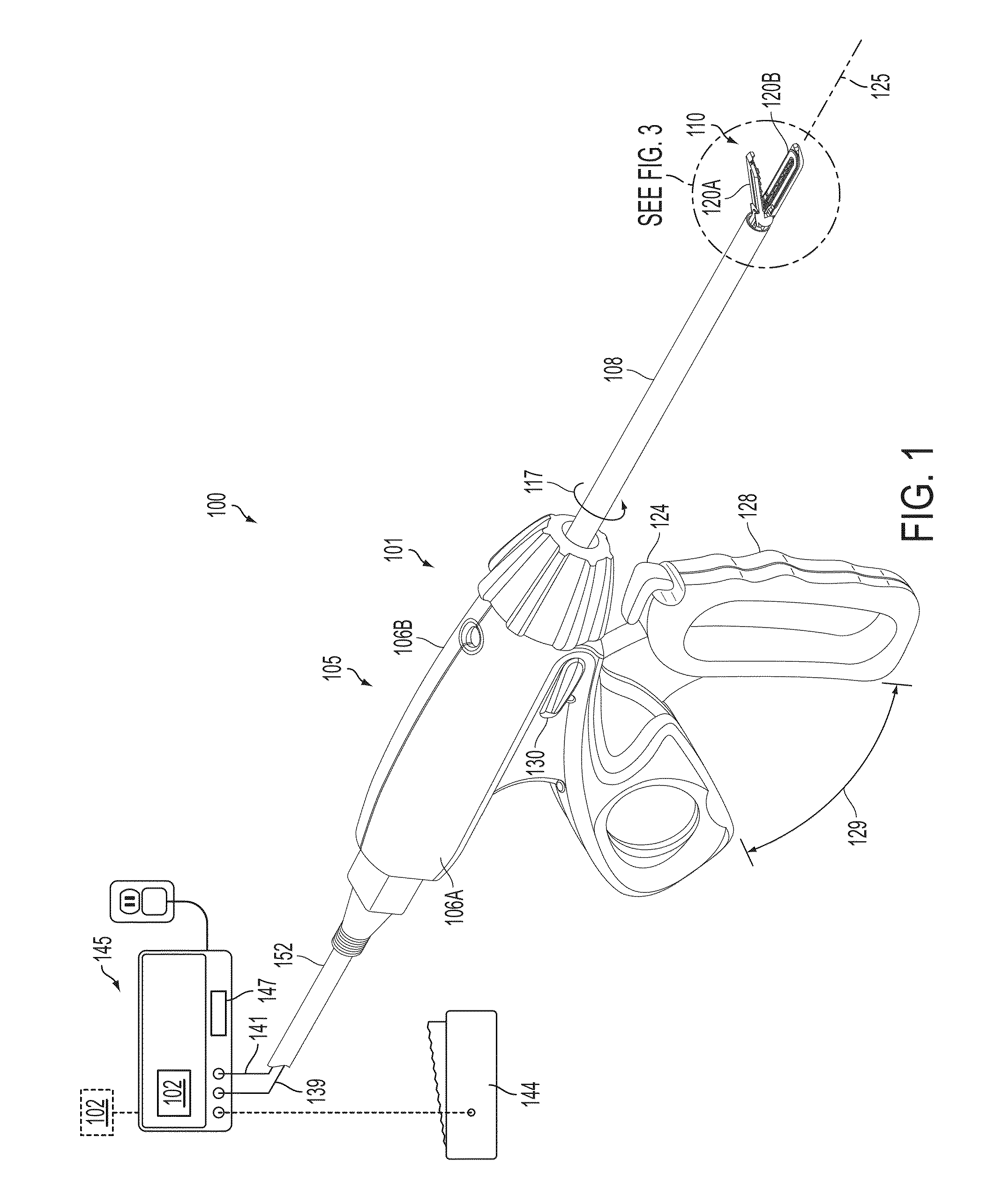
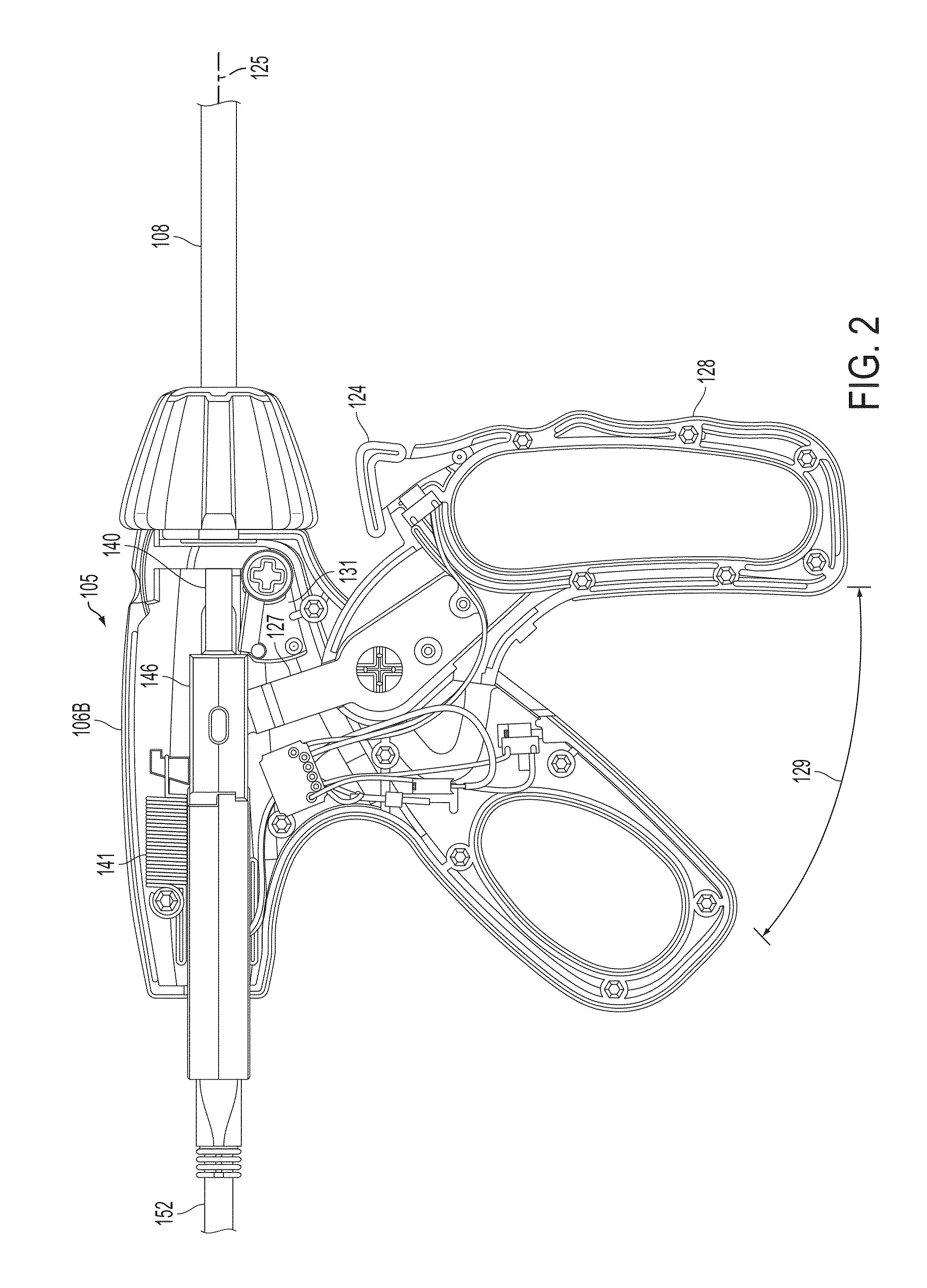
[0062]Various embodiments are directed to apparatuses, systems, and methods for the treatment of tissue. Numerous specific details are set forth to provide a thorough understanding of the overall structure, function, manufacture, and use of the embodiments as described in the specification and illustrated in the accompanying drawings. It will be understood by those skilled in the art, however, that the embodiments may be practiced without such specific details. In other instances, well-known operations, components, and elements have not been described in detail so as not to obscure the embodiments described in the specification. Those of ordinary skill in the art will understand that the embodiments described and illustrated herein are non-limiting examples, and thus it can be appreciated that the specific structural and functional details disclosed herein may be representative and illustrative. Variations and changes thereto may be made without departing from the scope of the claim...


PUM


Abstract

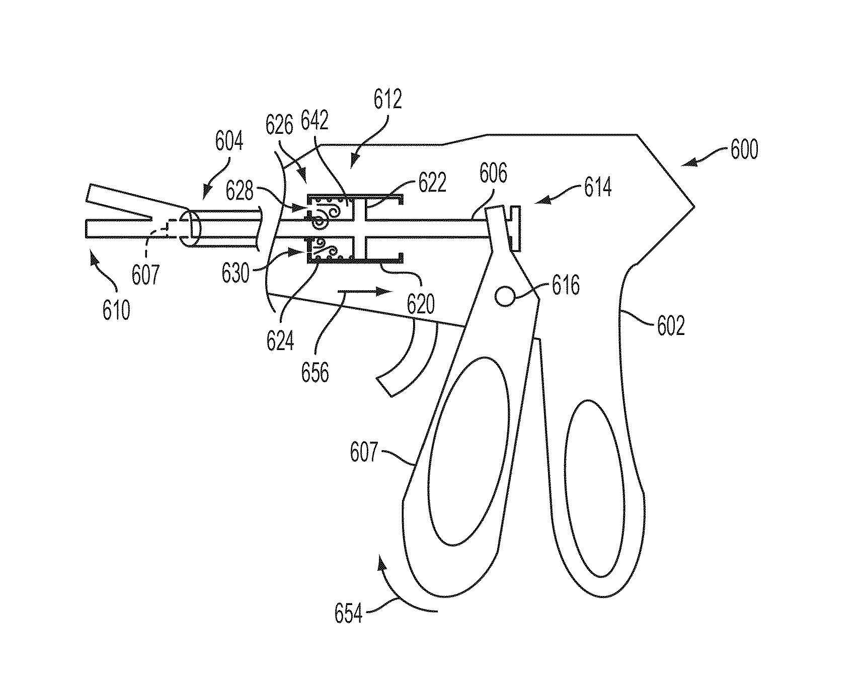
A surgical instrument for supplying energy to tissue can comprise a jaw member comprising an electrode, wherein the electrode is configured to supply energy from a power source to captured tissue. The surgical instrument comprises a tissue-cutting element to transect the captured tissue. The rate of distal translation of the tissue-cutting element during the operational stroke may be regulated by a damper. The damper may have barrel and a plunger.

Description

BACKGROUND[0001]The present invention relates to medical devices and methods. More particularly, the present invention relates to electrosurgical instruments and methods for sealing and transecting tissue.[0002]In various circumstances, a surgical instrument can be configured to apply energy to tissue in order to treat and / or destroy the tissue. In certain circumstances, a surgical instrument can comprise one or more electrodes which can be positioned against and / or positioned relative to the tissue such that electrical current can flow from one electrode, through the tissue, and to the other electrode. The surgical instrument can comprise an electrical input, a supply conductor electrically coupled with the electrodes, and / or a return conductor which can be configured to allow current to flow from the electrical input, through the supply conductor, through the electrodes and the tissue, and then through the return conductor to an electrical output, for example. In various circumsta...

Claims


Application Information

Patent Timeline
IPC IPC(8): A61B18/14A61B17/32A61B18/00
CPCA61B18/1445A61B17/320092A61B2018/0063A61B2018/00196A61B2018/00601A61B2018/00702A61B2018/00791A61B2018/00875A61B2018/1455A61B2017/320095A61B2017/320094A61B2017/320093A61B2018/00773A61B18/1447A61B2018/00309A61B2018/00589A61B2018/00619
Inventor WOODRUFF, SCOTT A.WEIZMAN, PATRICK A.PAYNE, GWENDOLYN P.KORVICK, DONNA L.NORVELL, DAVID K.ZINGMAN, ARON O.
Owner CILAG GMBH INT
Why Eureka
Try Eureka